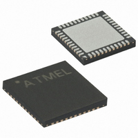
ATMEGA64RZAV-10MU Atmel, ATMEGA64RZAV-10MU Datasheet - Page 51

ATMEGA64RZAV-10MU
Manufacturer Part Number
ATMEGA64RZAV-10MU
Description
MCU ATMEGA644/AT86RF230 44-QFN
Manufacturer
Atmel
Series
ATMEGAr
Datasheets
1.ATMEGA644-20MU.pdf
(23 pages)
2.ATMEGA644-20MU.pdf
(376 pages)
3.AT86RF230-ZU.pdf
(98 pages)
Specifications of ATMEGA64RZAV-10MU
Frequency
2.4GHz
Modulation Or Protocol
802.15.4 Zigbee
Power - Output
3dBm
Sensitivity
-101dBm
Voltage - Supply
1.8 V ~ 3.6 V
Data Interface
PCB, Surface Mount
Memory Size
64kB Flash, 2kB EEPROM, 4kB RAM
Antenna Connector
PCB, Surface Mount
Package / Case
44-VFQFN Exposed Pad
Wireless Frequency
2.4 GHz
Interface Type
JTAG, SPI
Output Power
3 dBm
For Use With
ATSTK600-TQFP32 - STK600 SOCKET/ADAPTER 32-TQFP770-1005 - ISP 4PORT FOR ATMEL AVR MCU JTAG770-1004 - ISP 4PORT FOR ATMEL AVR MCU SPIATAVRISP2 - PROGRAMMER AVR IN SYSTEMATJTAGICE2 - AVR ON-CHIP D-BUG SYSTEMATSTK500 - PROGRAMMER AVR STARTER KIT
Lead Free Status / RoHS Status
Lead free / RoHS Compliant
Operating Temperature
-
Applications
-
Data Rate - Maximum
-
Current - Transmitting
-
Current - Receiving
-
Lead Free Status / Rohs Status
Lead free / RoHS Compliant
For Use With/related Products
ATmega64
8.3.3 Data Interpretation
8.3.4 Register Description
8.4 Received Signal Strength Indicator (RSSI)
5131E-MCU Wireless-02/09
Bit
0x07
Read/Write
Reset value
The measurement result is stored to register 0x07 (PHY_ED_LEVEL) 140 µs after its
initialization. The value is always 0 if the AT86RF230 is not in any of the RX states.
Thus by using Basic Operating Mode, a valid ED value from the currently received
frame is accessible 140 µs after the RX_START interrupt and remains valid until a new
RX_START interrupt is generated by the next incoming frame or until another ED
measurement is initiated manually.
By using the Extended Operating Mode, the RX_START interrupt is always masked
and cannot be used as timing reference. Here successful frame reception is only
signalized by the TRX_END interrupt. The minimum time between a TRX_END
interrupt and a following SFD detection is 96 µs. Including the ED measurement time,
the ED value needs to be read within 224 µs after the TRX_END interrupt; otherwise, it
could be overwritten by the result of the next measurement cycle.
Note, it is not recommended to initiate manually an ED measurement when using the
Extended Operating Mode.
The PHY_ED_LEVEL is an 8 bit register. The ED value of the AT86RF230 radio
transceiver has a valid range from 0 to 84 with a resolution of 1 dB. All other values do
not occur. If zero is read from the PHY_ED_LEVEL register, this indicates that the
measured energy is less than -91 dBm (see parameter 11.7.16). Due to environmental
conditions (temperature, voltage, semiconductor parameters, etc.) the computed energy
value has an accuracy of ±5 dBm, this is to be considered as constant offset over the
measurement range.
Register 0x07 (PHY_ED_LEVEL)
The ED_LEVEL register contains the result after an ED measurement.
• Bit [7:0] – ED_LEVEL
The minimum ED value (ED_LEVEL = 0) indicates receiver power less than
RSSI_BASE_VAL. The range is 84 dB with a resolution of 1 dB and an absolute
accuracy of ±5 dB. The measurement period is 8 symbol periods.
A manual ED measurement can be initiated by a write access to the register.
The Received Signal Strength Indicator main features are:
• Minimum RSSI sensitivity is -91 dBm (RSSI_BASE_VAL, see parameter 11.7.16)
• Dynamic range is 81 dB
• Minimum RSSI value is 0
• Maximum RSSI value is 28
R
7
0
R
6
0
R
5
0
ED_LEVEL[7:0]
R
4
0
R
3
0
R
2
0
R
1
0
AT86RF230
R
0
0
ED_LEVEL
51


