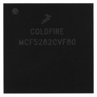
MCF5282CVF80 Freescale Semiconductor, MCF5282CVF80 Datasheet - Page 482

MCF5282CVF80
Manufacturer Part Number
MCF5282CVF80
Description
IC MPU 32BIT 66MHZ 256-MAPBGA
Manufacturer
Freescale Semiconductor
Series
MCF528xr
Datasheet
1.MCF5216CVM66J.pdf
(766 pages)
Specifications of MCF5282CVF80
Core Processor
Coldfire V2
Core Size
32-Bit
Speed
80MHz
Connectivity
CAN, EBI/EMI, Ethernet, I²C, SPI, UART/USART
Peripherals
DMA, LVD, POR, PWM, WDT
Number Of I /o
142
Program Memory Size
512KB (512K x 8)
Program Memory Type
FLASH
Ram Size
64K x 8
Voltage - Supply (vcc/vdd)
2.7 V ~ 3.6 V
Data Converters
A/D 8x10b
Oscillator Type
External
Operating Temperature
-40°C ~ 85°C
Package / Case
256-MAPBGA
Controller Family/series
ColdFire
Ram Memory Size
64KB
Embedded Interface Type
CAN, I2C, SPI, UART
No. Of Pwm Channels
8
Digital Ic Case Style
MAPBGA
Rohs Compliant
No
Package
256MA-BGA
Device Core
ColdFire
Family Name
MCF528x
Maximum Speed
80 MHz
Operating Supply Voltage
3.3 V
Data Bus Width
32 Bit
Number Of Programmable I/os
150
Interface Type
CAN/Ethernet/I2C/QSPI/UART
On-chip Adc
8-chx10-bit
Number Of Timers
12
Lead Free Status / RoHS Status
Contains lead / RoHS non-compliant
Eeprom Size
-
Available stocks
Company
Part Number
Manufacturer
Quantity
Price
Company:
Part Number:
MCF5282CVF80
Manufacturer:
FREESCALE
Quantity:
12 388
Company:
Part Number:
MCF5282CVF80
Manufacturer:
Freescale Semiconductor
Quantity:
10 000
Company:
Part Number:
MCF5282CVF80J
Manufacturer:
Freescale Semiconductor
Quantity:
10 000
- Current page: 482 of 766
- Download datasheet (9Mb)
FlexCAN
A received remote frame is not stored in a receive message buffer. It is only used to trigger the automatic
transmission of a frame in response. The mask registers are not used in remote frame ID matching. All ID
bits (except RTR) of the incoming received frame must match for the remote frame to trigger a response
transmission.
25.4.5
Overload frame transmissions are not initiated by the FlexCAN unless certain conditions are detected on
the CAN bus. These conditions include:
25.4.6
The value of the free-running 16-bit timer is sampled at the beginning of the identifier field on the CAN
bus. For a message being received, the time stamp will be stored in the time stamp entry of the receive
message buffer at the time the message is written into that buffer. For a message being transmitted, the time
stamp entry will be written into the transmit message buffer once the transmission has completed
successfully.
The free-running timer can optionally be reset upon the reception of a frame into message buffer 0. This
feature allows network time synchronization to be performed.
25.4.7
In listen-only mode, the FlexCAN module is able to receive messages without giving an acknowledgment.
Whenever the module enters this mode the status of the Error Counters is frozen and the FlexCAN module
operates like in error passive mode. Since the module does not influence the CAN bus in this mode the
host device is capable of functioning like a monitor or for automatic bit-rate detection.
25.4.8
The FlexCAN module uses three 8-bit registers to set up the bit timing parameters required by the CAN
protocol. Control registers 1 and 2 (CANCTRL1, CANCTRL2) contain the PROPSEG, PSEG1, PSEG2,
and the RJW fields which allow the user to configure the bit timing parameters. The prescaler divide
register (PRESDIV) allows the user to select the ratio used to derive the S-clock from the system clock.
The time quanta clock operates at the S-clock frequency.
CAN bit rate, and S-clock bit timing parameters.
25-12
•
•
•
Detection of a dominant bit in the first or second bit of intermission.
Detection of a dominant bit in the seventh (last) bit of the end-of-frame (EOF) field in receive
frames.
Detection of a dominant bit in the eighth (last) bit of the error frame delimiter or overload frame
delimiter.
Overload Frames
Time Stamp
Listen-Only Mode
Bit Timing
MCF5282 and MCF5216 ColdFire Microcontroller User’s Manual, Rev. 3
Table 25-7
provides examples of system clock,
Freescale Semiconductor
Related parts for MCF5282CVF80
Image
Part Number
Description
Manufacturer
Datasheet
Request
R
Part Number:
Description:
Mcf5282 And Mcf5216 Coldfire Microcontroller Userís Manual
Manufacturer:
Freescale Semiconductor, Inc
Datasheet:
Part Number:
Description:
Manufacturer:
Freescale Semiconductor, Inc
Datasheet:
Part Number:
Description:
Manufacturer:
Freescale Semiconductor, Inc
Datasheet:
Part Number:
Description:
Manufacturer:
Freescale Semiconductor, Inc
Datasheet:
Part Number:
Description:
Manufacturer:
Freescale Semiconductor, Inc
Datasheet:
Part Number:
Description:
Manufacturer:
Freescale Semiconductor, Inc
Datasheet:
Part Number:
Description:
Manufacturer:
Freescale Semiconductor, Inc
Datasheet:
Part Number:
Description:
Manufacturer:
Freescale Semiconductor, Inc
Datasheet:
Part Number:
Description:
Manufacturer:
Freescale Semiconductor, Inc
Datasheet:
Part Number:
Description:
Manufacturer:
Freescale Semiconductor, Inc
Datasheet:
Part Number:
Description:
Manufacturer:
Freescale Semiconductor, Inc
Datasheet:
Part Number:
Description:
Manufacturer:
Freescale Semiconductor, Inc
Datasheet:
Part Number:
Description:
Manufacturer:
Freescale Semiconductor, Inc
Datasheet:
Part Number:
Description:
Manufacturer:
Freescale Semiconductor, Inc
Datasheet:
Part Number:
Description:
Manufacturer:
Freescale Semiconductor, Inc
Datasheet:


