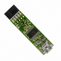
DLP-USB232M-G DLP Design Inc, DLP-USB232M-G Datasheet - Page 7

DLP-USB232M-G
Manufacturer Part Number
DLP-USB232M-G
Description
MODULE USB-TO-TTL SRL UART CONV
Manufacturer
DLP Design Inc
Series
DLP-USB232Mr
Datasheet
1.DLP-USB232M-G.pdf
(12 pages)
Specifications of DLP-USB232M-G
Convert From (adapter End)
USB
Convert To (adapter End)
DB9 Female
Features
Integrated 6MHz-48MHz clock multiplier PLL
Interface Type
USB
Data Bus Width
8 bit
Product
Interface Modules
For Use With/related Products
Windows® 98 or higher, Mac OS 8.5 or higher
Lead Free Status / RoHS Status
Lead free / RoHS Compliant
Lead Free Status / RoHS Status
Lead free / RoHS Compliant, Lead free / RoHS Compliant
Other names
813-1018
DLP-USB232M User’s Manual
Figure 3 shows how to configure the DLP-USB232M to interface with a 3.3v logic device in Bus-Powered
configuration. In this example, a LDO regulator provides 3.3 volts from the USB Bus to the target microcontroller and
the VCCIO line (pin 10) which in turn will cause the UART interface IO pins to drive out at 3.3v level.
Figure 3
Figure 4
Bus Powered Circuit with Power Control
USB Bus powered circuits need to be able to power down
in USB suspend mode in order to meet the <= 500uA total
suspend current requirement (including external logic).
Figure 4 shows how to use a discrete P-Channel Logic Level
MOSFET to control the power to external logic circuits. A
suitable device could be a Fairchild NDT456P or equivalent.
This configuration is suitable for powering external logic
where the normal supply current is <= 100mA and the logic
to be controlled does not generate an appreciable current
surge at power-up. For power switching external logic that
takes over 100mA or generates a current surge on powerup
we recommend that a dedicated power switch i.c with
inbuilt “soft-start” is used instead of a MOSFET. A suitable
power switch i.c. for such an application would be a Micrel
(www.micrel.com) MIC2025-2BM or equivalent.
Copyright © DLP Design 2002
Page 7 of 12


