DLP-USB1232H DLP Design Inc, DLP-USB1232H Datasheet
DLP-USB1232H
Specifications of DLP-USB1232H


Related parts for DLP-USB1232H


DLP-USB1232H Summary of contents
Page 1
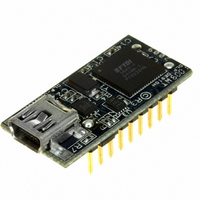
... USB1232H is available in a lead-free, RoHS-compliant, compact 18-pin, 0.1-inch spaced standard DIP footprint. FEATURES: The DLP-USB1232H has the capability of being configured in a variety of industry standard serial or parallel interfaces supporting these features: • Entire USB protocol handled on the module. No USB specific firmware programming required. ...
Page 2
... Windows CE 4.2, 5.0, 5.2 and 6.0 • Linux 2.4 or later and Linux x86_64 The drivers listed above are all available for free download from the DLP Design website www.dlpdesign.com and FTDI website www.ftdichip.com. Various third-party drivers are also available for other operating systems; see the FTDI website www ...
Page 3
... USB silicon. It has the capability of being configured in a variety of industry standard serial or parallel interfaces. The DLP-USB1232H can be configured for UART, FIFO, JTAG, SPI, I2C or bit-bang mode. In addition to these, the DLP-USB1232H supports a CPU interface FIFO mode. Refer to the FT2232H datasheet for additional detail on how to set up and use the supported modes ...
Page 4
... PIN DESCRIPTIONS This section describes the operation of the DLP-USB1232H pins. The function of the I/O pins is determined by the configuration that is stored in the EEPROM connected to the FT2232H USB IC. The following table details the function of each pin for the specified mode. Note that the convention used throughout this document for active low signals is the signal name followed ...
Page 5
... Pre-Charge Time T9 Valid Data Setup to WR Falling Edge* T10 Valid Data Hold Time from WR Inactive* T11 WR Inactive to TXE# T12 TXE# Inactive After WR Cycle *Load = 30pF Rev. 1.3 (December 2009 Valid data N N T11 T7 T9 Valid data T12 T8 T10 © DLP Design, Inc. ...
Page 6
... Once loaded, the VCP drivers will allow your application software—running on the host PC—to communicate with the DLP-USB1232H as though it were connected to a COM (RS-232) port. In addition to VCP drivers, FTDI's D2XX direct drivers for Windows offer an alternative solution to the VCP drivers that allow application software to interface with the FT2232H device using a DLL instead of a Virtual COM Port ...
Page 7
... Download the latest CDM device drivers from either www.dlpdesign.com or www.ftdichip.com. Unzip the drivers into a folder on the hard drive. 2. Connect the DLP-USB1232H module to the PC via a USB ‘A’ to mini-B cable. This action initiates the loading of the USB drivers. When prompted, select the folder where the device drivers were stored in Step 1 ...
Page 8
... USB host from Suspend Mode by strobing this pin low for a minimum of 20ms which will cause the device to request a resume on the USB bus. 16 DB1 - FIFO Data Bus Bit 1 17 DB4 - FIFO Data Bus Bit 4 18 DB0 - FIFO Data Bus Bit 0 Rev. 1.3 (December 2009 © DLP Design, Inc. ...
Page 9
... DCD# - Data Carrier Detect Control Input 14 WRSTB TXDEN - (TTL level). For use with RS485 level converters. 16 RXD - Receiving Asynchronous Data Input 17 DTR# - Data Terminal Ready Control Output/Handshake Signal 18 TXD - Transmit Asynchronous Data Output Rev. 1.3 (December 2009 © DLP Design, Inc. ...
Page 10
... USB bus. Figure 3. Figure 3 shows how to configure the DLP-USB1232H to interface with a microcontroller via the parallel 245 FIFO interface mode. In this example, the target electronics can operate at from 3 ...
Page 11
... Figure 4. Figure 4 shows how to configure the DLP-USB1232H to interface with a 3.3V logic device via the ASYNC serial mode. In this example, the target electronics provide the 3.3 volts to power the microcontroller. 9.0 BUS-POWERED CIRCUIT WITH POWER CONTROL USB bus-powered circuits need to be able to power down in USB Suspend Mode in order to meet the Suspend current requirement (including external logic): Figure 4 ...
Page 12
... This product and its documentation are supplied on an as-is basis, and no warranty as to their suitability for any particular purpose is either made or implied. DLP Design, Inc. will not accept any claim for damages whatsoever arising as a result of the use or failure of this product. Your statutory rights are not affected ...
Page 13
... This document provides preliminary information that may be subject to change without notice. 12.0 CONTACT INFORMATION DLP Design, Inc. 1605 Roma Lane Allen, TX 75013 Phone: 469-964-8027 Fax: 415-901-4859 Email Sales: sales@dlpdesign.com Email Support: support@dlpdesign.com Website URL: http://www.dlpdesign.com Rev. 1.3 (December 2009) 13 © DLP Design, Inc. ...
Page 14
AGND 1 GND 5 GND 11 GND 15 GND 25 GND 35 GND 47 GND 51 GND 4 VPHY 9 VPLL 12 VCORE 37 VCORE 64 VCORE 20 VCCIO 31 VCCIO 42 VCCIO 56 VCCIO ...