DLP-USB245R DLP Design Inc, DLP-USB245R Datasheet
DLP-USB245R
Specifications of DLP-USB245R


Related parts for DLP-USB245R


DLP-USB245R Summary of contents
Page 1
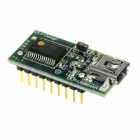
... FT245R IC with FTDIChip-ID™ feature from FTDI. In addition to enabling standard USB-to-FIFO designs, both asynchronous and synchronous bit-bang interface modes are also available. The DLP-USB245R is available in a lead-free, RoHS-compliant, compact 18-pin, 0.1-inch standard DIP footprint. FEATURES: • Single-chip USB-to-parallel FIFO bidirectional data-transfer interface. ...
Page 2
... Windows CE 4.2, 5.0 and 6.0 • Linux 2.4 and greater The drivers listed above are all available for free download from the DLP Design website www.dlpdesign.com and FTDI website www.ftdichip.com. Various third-party drivers are also available for other operating systems; see the FTDI website www ...
Page 3
... Operating Supply Current • Operating Supply Current 1.0 GENERAL DESCRIPTION The DLP-USB245M provides an easy, cost-effective method of transferring data to/from a peripheral and a host million bits (1 megabyte) per second. Its simple, FIFO-like design makes it easy to interface to any microcontroller or microprocessor via I/O ports. ...
Page 4
... Pre-Charge Time T9 Valid Data Setup to WR Falling Edge* T10 Valid Data Hold Time from WR Inactive* T11 WR Inactive to TXE# T12 TXE# Inactive After WR Cycle *Load = 30pF Rev. 1.0 (November 2008 Valid data N N T11 T7 T9 Valid data T12 T8 T10 © DLP Design, Inc. ...
Page 5
... Once loaded, the VCP drivers will allow your application software—running on the host PC—to communicate with the DLP-USB245R as though it were connected to a COM (RS-232) port. In addition to VCP drivers, FTDI's D2XX direct drivers for Windows offer an alternative solution to the VCP drivers that allow application software to interface with the FT245R device using a DLL instead of a Virtual COM Port ...
Page 6
... Download the CDM device drivers from either www.dlpdesign.com or www.ftdichip.com. Unzip the drivers into a folder on the hard drive. 2. Connect the DLP-USB245R board to the PC via a USB ‘A’ to mini-B cable. This action initiates the loading of the USB drivers. When prompted, select the folder where the device drivers were stored in Step 1 ...
Page 7
... USB host from Suspend Mode by strobing this pin low for a minimum of 20ms which will cause the device to request a resume on the USB bus. 16 DB1 - FIFO Data Bus Bit 1 17 DB4 - FIFO Data Bus Bit 4 18 DB0 - FIFO Data Bus Bit 0 Rev. 1.0 (November 2008) 7 © DLP Design, Inc. ...
Page 8
... EEPROM of the FT245R should be programmed to match the total current drawn by the target system. Note: If using PWREN# (available using the CBUS), the I/O pin should be pulled to VCCIO using a 10k-ohm resistor. Rev. 1.0 (November 2008 Bus-Powered 5V System 8 © DLP Design, Inc. ...
Page 9
... Figure 3. 3.3V Figure 3 shows how to configure the DLP-USB245R to interface with a 3.3V logic device. In this example, the target electronics provide the 3.3 volts via the VCCIO line (Pin 7) which, in turn, will cause the FT245R interface I/O pins to drive out at the 3.3V level. ...
Page 10
... FT245R EEPROM to inform the system of its power requirements. 4. PWREN# gets its VCC from VCCIO. For designs using 3.3-volt logic, ensure that VCCIO is not powered down during Suspend. Rev. 1.0 (November 2008) P-Channel Power MOSFET .1uF 10K 1K VCC PWREN Power Controlled by PWREN# 10 Microcontroller © DLP Design, Inc. ...
Page 11
... This product and its documentation are supplied on an as-is basis, and no warranty as to their suitability for any particular purpose is either made or implied. DLP Design, Inc. will not accept any claim for damages whatsoever arising as a result of the use or failure of this product. Your statutory rights are not affected ...
Page 12
... This document provides preliminary information that may be subject to change without notice. 12.0 CONTACT INFORMATION DLP Design, Inc. 1605 Roma Lane Allen, TX 75013 Phone: 469-964-8027 Fax: 415-901-4859 Email Sales: sales@dlpdesign.com Email Support: support@dlpdesign.com Website URL: http://www.dlpdesign.com Rev. 1.0 (November 2008) 12 © DLP Design, Inc. ...
Page 13
AGND 7 GND 18 GND 21 GND 26 TEST 4 VCCIO ...