DLP-USB232M-G DLP Design Inc, DLP-USB232M-G Datasheet
DLP-USB232M-G
Specifications of DLP-USB232M-G


Related parts for DLP-USB232M-G


DLP-USB232M-G Summary of contents
Page 1
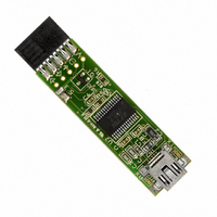
... DLP-USB232M-G USB – SERIAL UART Interface Module The DLP-USB232M-G lead free module uses FTDI’s 2nd generation FT232BM USB-UART chip that adds extra functionality to its predecessor (the FT8U232AM) and reduces external component count. HARDWARE FEATURES • Single Chip USB Asynchronous Serial Data Transfer • ...
Page 2
... High ). In this mode, any residual voltage on external circuitry is bled to GND when power is removed thus ensuring that external circuitry controlled by PWREN# resets reliably when power is restored. Copyright © DLP Design 2002 DLP-USB232M User’s Manual • Lower Suspend Current Integration of RCCLK within the device and internal design improvements reduce the suspend current of the FT232BM to under 200uA ( excluding the 1 ...
Page 3
... For instance, it may be possible to connect the device to an SRAM configurable Copyright © DLP Design 2002 DLP-USB232M User’s Manual FPGA as supplied by vendors such as Altera and Xilinx. The FPGA device would normally be un-configured ( i.e. ...
Page 4
... Table 1 - DLP-USB232M PINOUT DESCRIPTION Pin# Description 1 BOARD ID (Out) Identifies the board as either a DLP-USB245M or DLP-USB232M. High for DLP- USB232M and low for DLP-USB245M. 2 Ground 3 RESET# (In) Can be used by an external device to reset the FT245BM. If not required, this pin must be tied to VCC. 4 RESETO# (Out) Output of the internal Reset Generator. Stays high impedance for ~ 2ms after VCC > ...
Page 5
... Terminal Ready Control Output / Handshake signal 21 CTS# (IN) Clear To Send Control Input / Handshake signal 22 RTS# (OUT) Request To Send Control Output / Handshake signal 23 RXD (IN) Receive Asynchronous Data Input 24 TXD (OUT)Transmit Asynchronous Data Output Copyright © DLP Design 2002 DLP-USB232M User’s Manual Page ...
Page 6
... A Self Powered Device can take as much current as it likes during normal operation and USB suspend as it has its own Power Supply Self Powered Device can be used with any USB Host and both Bus and Self Powered USB Hubs. Copyright © DLP Design 2002 DLP-USB232M User’s Manual Figure 1 illustrates a typical USB bus powered configuration. A USB Bus Powered device gets its power from the USB bus. Basic rules for USB Bus power devices are as follows – ...
Page 7
... Figure 3 shows how to configure the DLP-USB232M to interface with a 3.3v logic device in Bus-Powered configuration. In this example, a LDO regulator provides 3.3 volts from the USB Bus to the target microcontroller and the VCCIO line (pin 10) which in turn will cause the UART interface IO pins to drive out at 3.3v level. ...
Page 8
... For 3.3v power controlled circuits VCCIO must not be powered down with the external circuitry (PWREN# gets it’s VCC supply from VCCIO). MECHANICAL DRAWINGS (PRELIMINARY) INCHES (MILLIMETERS) UNLESS OTHERWISE NOTED 1.5 typ (38.1 typ) Copyright © DLP Design 2002 .235 typ (6.0 typ) .50 typ (12.7 typ) .19 typ dia ( ...
Page 9
... These are the absolute maximum ratings for the DLP-USB232M module in accordance with the Absolute Maximum Rating System (IEC 60134). Exceeding these may cause permanent damage to the device. • Storage Temperature ……………………………………………………. –65 • ...
Page 10
... UDrvZ Driver Output Impedance Note 1 – Inputs have an internal 200k pull-up resistor to VCCIO. Note 2 – Driver Output Impedance includes the external 27R series resistors on USBDP and USBDM pins. Copyright © DLP Design 2002 DLP-USB232M User’s Manual Min Typ Max Units 1 ...
Page 11
... This product and its documentation are supplied basis and no warranty as to their suitability for any particular purpose is either made or implied. DLP Design will not accept any claim for damages howsoever arising as a result of use or failure of this product. Your statutory rights are not affected. ...
Page 12
GND 29 AGND 9 GND 17 GND 30 AVCC 3 VCC 26 VCC 13 VCC-IO ...