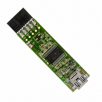
DLP-USB232M-G DLP Design Inc, DLP-USB232M-G Datasheet - Page 5

DLP-USB232M-G
Manufacturer Part Number
DLP-USB232M-G
Description
MODULE USB-TO-TTL SRL UART CONV
Manufacturer
DLP Design Inc
Series
DLP-USB232Mr
Datasheet
1.DLP-USB232M-G.pdf
(12 pages)
Specifications of DLP-USB232M-G
Convert From (adapter End)
USB
Convert To (adapter End)
DB9 Female
Features
Integrated 6MHz-48MHz clock multiplier PLL
Interface Type
USB
Data Bus Width
8 bit
Product
Interface Modules
For Use With/related Products
Windows® 98 or higher, Mac OS 8.5 or higher
Lead Free Status / RoHS Status
Lead free / RoHS Compliant
Lead Free Status / RoHS Status
Lead free / RoHS Compliant, Lead free / RoHS Compliant
Other names
813-1018
10
11
12
13
14
15
16
17
18
19
20
21
22
23
24
VCC-IO
When interfacing with 3.3v external logic connect VCC-IO to the 3.3v supply of the external logic,
otherwise connect to VCC to drive out at 5v CMOS level. This pin must be connected to VCC from
the target electronics or EXTVCC.
EXTVCC
PORTVCC if module is to be powered by the USB port (typical configuration)
PORTVCC
USB port (typical configuration). 500mA maximum current available to USB adapter and target
electronics if USB device is configured for high power.
TXLED#
PWRCTL
POWEREN#
suspend. Can be used to control power to external logic using a P-Channel Logic Level
MOSFET switch. Enable the Interface Pull-Down Option in EEPROM when using the PWREN# pin
in this way.
TXDEN
RI# (IN) Ring Indicator Control Input. When the Remote Wakeup option is enabled in the
EEPROM, taking RI# low can be used to resume the PC USB Host controller from suspend.
DCD#
DSR#
DTR#
CTS#
RTS#
RXD
TXD
Copyright © DLP Design 2002
(OUT)Transmit Asynchronous Data Output
(IN) Receive Asynchronous Data Input
(IN) Clear To Send Control Input / Handshake signal
(OUT) Request To Send Control Output / Handshake signal
(OUT)Data Terminal Ready Control Output / Handshake signal
(IN)Data Set Ready Control Input / Handshake signal
(IN)Data Carrier Detect Control Input
(OUT) Enable Transmit Data for RS485
(In) 3.0 volt to +5.25 volt VCC to the UART interface pins 10..12, 14..16 and 18..25.
- (O.C.) LED Drive - Pulses Low when Transmitting Data via USB
– (In) Use for applying main power (4.4 to 5.25 Volts) to the module. Connect to
(IN) Bus Powered – Tie Low / Self Powered – Tie High
- (Out) Power from USB port. Connect to EXTVCC if module is to be powered by the
(OUT) Goes Low after the device is configured via USB, then high during USB
DLP-USB232M User’s Manual
Page 5 of 12


