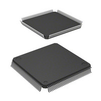
HD6417708RF100A Renesas Electronics America, HD6417708RF100A Datasheet - Page 231

HD6417708RF100A
Manufacturer Part Number
HD6417708RF100A
Description
IC SUPERH MPU ROMLESS 144LQFP
Manufacturer
Renesas Electronics America
Series
SuperH® SH7700r
Datasheet
1.HD6417708SF60V.pdf
(635 pages)
Specifications of HD6417708RF100A
Core Processor
SH-2
Core Size
32-Bit
Speed
100MHz
Connectivity
EBI/EMI, SCI, SmartCard
Peripherals
POR, WDT
Number Of I /o
8
Program Memory Type
ROMless
Voltage - Supply (vcc/vdd)
3.15 V ~ 3.6 V
Oscillator Type
External
Operating Temperature
-20°C ~ 75°C
Package / Case
144-LQFP
Lead Free Status / RoHS Status
Contains lead / RoHS non-compliant
Eeprom Size
-
Ram Size
-
Program Memory Size
-
Data Converters
-
Available stocks
Company
Part Number
Manufacturer
Quantity
Price
Company:
Part Number:
HD6417708RF100A
Manufacturer:
Renesas Electronics America
Quantity:
10 000
Part Number:
HD6417708RF100A
Manufacturer:
HITACHI/日立
Quantity:
20 000
Part Number:
HD6417708RF100AV
Manufacturer:
RENESAS/瑞萨
Quantity:
20 000
- Current page: 231 of 635
- Download datasheet (3Mb)
Bits 11 and 10—Write-Precharge Delay (TRWL1, TRWL0): These bits set the synchronous
DRAM write-precharge delay time. This designates the time between the end of a write cycle and
the next bank-active command. This is valid only when synchronous DRAM is connected. After
the write cycle, the next bank-active command is not issued for the period TPC + TRWL.
Bit 11: TRWL1
0
1
Bits 9 and 8—CAS-Before-RAS Refresh RAS Assert Time (TRAS1, TRAS0): When DRAM
interface is selected as connected memory, the TRAS bits set the RAS assertion period for CAS-
before-RAS refreshes. When pseudo-SRAM interface is selected, they set the OE/RFSH assertion
period for auto-refreshes. When synchronous DRAM interface is selected, no bank-active
command is issued during the period TPC + TRAS after an auto-refresh command.
In the SH7708, set the same values in the TRAS bits in MCR and DCR.
Bit 9: TRAS1
0
1
Bit 7—Reserved: This bit always reads 0. The write value should always be 0.
Bit 6—Burst Enable (BE): Specifies whether to conduct a burst access of DRAM or pseudo-
SRAM. When accessing synchronous DRAM, burst access is always carried out, regardless of this
bit’s designation.
Bit 6: BE
0
1
Bit 10: TRWL0
0
1
0
1
Bit 8: TRAS0
0
1
0
1
Description
Burst disabled
With DRAM interface, high-speed page mode access
With pseudo-SRAM interface, continuous data transfer in static column
mode
Description
1 cycle
2 cycles
3 cycles
Reserved (cannot be set)
Description
2 cycles
3 cycles
4 cycles
5 cycles
(Initial value)
(Initial value)
(Initial value)
211
Related parts for HD6417708RF100A
Image
Part Number
Description
Manufacturer
Datasheet
Request
R

Part Number:
Description:
KIT STARTER FOR M16C/29
Manufacturer:
Renesas Electronics America
Datasheet:

Part Number:
Description:
KIT STARTER FOR R8C/2D
Manufacturer:
Renesas Electronics America
Datasheet:

Part Number:
Description:
R0K33062P STARTER KIT
Manufacturer:
Renesas Electronics America
Datasheet:

Part Number:
Description:
KIT STARTER FOR R8C/23 E8A
Manufacturer:
Renesas Electronics America
Datasheet:

Part Number:
Description:
KIT STARTER FOR R8C/25
Manufacturer:
Renesas Electronics America
Datasheet:

Part Number:
Description:
KIT STARTER H8S2456 SHARPE DSPLY
Manufacturer:
Renesas Electronics America
Datasheet:

Part Number:
Description:
KIT STARTER FOR R8C38C
Manufacturer:
Renesas Electronics America
Datasheet:

Part Number:
Description:
KIT STARTER FOR R8C35C
Manufacturer:
Renesas Electronics America
Datasheet:

Part Number:
Description:
KIT STARTER FOR R8CL3AC+LCD APPS
Manufacturer:
Renesas Electronics America
Datasheet:

Part Number:
Description:
KIT STARTER FOR RX610
Manufacturer:
Renesas Electronics America
Datasheet:

Part Number:
Description:
KIT STARTER FOR R32C/118
Manufacturer:
Renesas Electronics America
Datasheet:

Part Number:
Description:
KIT DEV RSK-R8C/26-29
Manufacturer:
Renesas Electronics America
Datasheet:

Part Number:
Description:
KIT STARTER FOR SH7124
Manufacturer:
Renesas Electronics America
Datasheet:

Part Number:
Description:
KIT STARTER FOR H8SX/1622
Manufacturer:
Renesas Electronics America
Datasheet:

Part Number:
Description:
KIT DEV FOR SH7203
Manufacturer:
Renesas Electronics America
Datasheet:


