HD6417708RF100A Renesas Electronics America, HD6417708RF100A Datasheet - Page 153
HD6417708RF100A
Manufacturer Part Number
HD6417708RF100A
Description
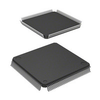
IC SUPERH MPU ROMLESS 144LQFP
Manufacturer
Renesas Electronics America
Series
SuperH® SH7700r
Datasheet
1.HD6417708SF60V.pdf
(635 pages)
Specifications of HD6417708RF100A
Core Processor
SH-2
Core Size
32-Bit
Speed
100MHz
Connectivity
EBI/EMI, SCI, SmartCard
Peripherals
POR, WDT
Number Of I /o
8
Program Memory Type
ROMless
Voltage - Supply (vcc/vdd)
3.15 V ~ 3.6 V
Oscillator Type
External
Operating Temperature
-20°C ~ 75°C
Package / Case
144-LQFP
Lead Free Status / RoHS Status
Contains lead / RoHS non-compliant
Eeprom Size
-
Ram Size
-
Program Memory Size
-
Data Converters
-
Available stocks
Company
Part Number
Manufacturer
Quantity
Price
Company:

Part Number:
HD6417708RF100A
Manufacturer:
Renesas Electronics America
Quantity:
10 000
Part Number:
HD6417708RF100A
Manufacturer:
HITACHI/日立
Quantity:
20 000
Part Number:
HD6417708RF100AV
Manufacturer:
RENESAS/瑞萨
Quantity:
20 000


Bit 10—PC Break Select A (PCBA): Selects whether to place the channel A instruction fetch
cycle break before or after instruction execution.
Bit 10: PCBA
0
1
Bits 9 and 8—Reserved: These bits always read 0. The write value should always be 0.
Bit 7—Data Break Enable B (DBEB): Selects whether to include data bus conditions in the
channel B break conditions.
Bit 7: DBEB
0
1
Note: When the data bus is not included in the break conditions, the IDB1 and IDB0 bits of break
Bit 6—PC Break Select B (PCBB): Selects whether to place the channel B instruction fetch cycle
break before or after instruction execution
Bit 6: PCBB
0
1
Bits 5 and 4—Reserved: These bits always read 0. The write value should always be 0.
Bit 3—Sequence Condition Select (SEQ): Selects whether to handle the channel A and B
conditions independently or sequentially. When set for sequential, the CMFB flag is set when the
channel B condition is matched after the channel A condition has already been matched.
Bit 3: SEQ
0
1
Bits 2 to 0—Reserved: These bits always read 0. The write value should always be 0.
bus cycle register B (BBRB) should be 10 or 11.
Description
Places the channel A PC break before instruction execution.
Places the channel A PC break after instruction execution.
Description
Do not include data bus conditions in the channel B conditions.
Include data bus conditions in the channel B conditions.
Description
Places the channel B PC break before instruction execution.
Places the channel B PC break after instruction execution.
Description
Compare channel A and B conditions independently.
Compare channel A and B conditions sequentially (channel A, then
channel B).
(Initial value)
(Initial value)
(Initial value)
(Initial value)
133
Related parts for HD6417708RF100A
Image
Part Number
Description
Manufacturer
Datasheet
Request
R

Part Number:
Description:
KIT STARTER FOR M16C/29
Manufacturer:
Renesas Electronics America
Datasheet:

Part Number:
Description:
KIT STARTER FOR R8C/2D
Manufacturer:
Renesas Electronics America
Datasheet:

Part Number:
Description:
R0K33062P STARTER KIT
Manufacturer:
Renesas Electronics America
Datasheet:

Part Number:
Description:
KIT STARTER FOR R8C/23 E8A
Manufacturer:
Renesas Electronics America
Datasheet:

Part Number:
Description:
KIT STARTER FOR R8C/25
Manufacturer:
Renesas Electronics America
Datasheet:

Part Number:
Description:
KIT STARTER H8S2456 SHARPE DSPLY
Manufacturer:
Renesas Electronics America
Datasheet:

Part Number:
Description:
KIT STARTER FOR R8C38C
Manufacturer:
Renesas Electronics America
Datasheet:

Part Number:
Description:
KIT STARTER FOR R8C35C
Manufacturer:
Renesas Electronics America
Datasheet:

Part Number:
Description:
KIT STARTER FOR R8CL3AC+LCD APPS
Manufacturer:
Renesas Electronics America
Datasheet:
Part Number:
Description:
KIT STARTER FOR RX610
Manufacturer:
Renesas Electronics America
Datasheet:

Part Number:
Description:
KIT STARTER FOR R32C/118
Manufacturer:
Renesas Electronics America
Datasheet:

Part Number:
Description:
KIT DEV RSK-R8C/26-29
Manufacturer:
Renesas Electronics America
Datasheet:

Part Number:
Description:
KIT STARTER FOR SH7124
Manufacturer:
Renesas Electronics America
Datasheet:

Part Number:
Description:
KIT STARTER FOR H8SX/1622
Manufacturer:
Renesas Electronics America
Datasheet:

Part Number:
Description:
KIT DEV FOR SH7203
Manufacturer:
Renesas Electronics America
Datasheet: