HD6417708RF100A Renesas Electronics America, HD6417708RF100A Datasheet - Page 196
HD6417708RF100A
Manufacturer Part Number
HD6417708RF100A
Description
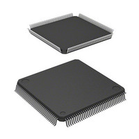
IC SUPERH MPU ROMLESS 144LQFP
Manufacturer
Renesas Electronics America
Series
SuperH® SH7700r
Datasheet
1.HD6417708SF60V.pdf
(635 pages)
Specifications of HD6417708RF100A
Core Processor
SH-2
Core Size
32-Bit
Speed
100MHz
Connectivity
EBI/EMI, SCI, SmartCard
Peripherals
POR, WDT
Number Of I /o
8
Program Memory Type
ROMless
Voltage - Supply (vcc/vdd)
3.15 V ~ 3.6 V
Oscillator Type
External
Operating Temperature
-20°C ~ 75°C
Package / Case
144-LQFP
Lead Free Status / RoHS Status
Contains lead / RoHS non-compliant
Eeprom Size
-
Ram Size
-
Program Memory Size
-
Data Converters
-
Available stocks
Company
Part Number
Manufacturer
Quantity
Price
Company:

Part Number:
HD6417708RF100A
Manufacturer:
Renesas Electronics America
Quantity:
10 000
Part Number:
HD6417708RF100A
Manufacturer:
HITACHI/日立
Quantity:
20 000
Part Number:
HD6417708RF100AV
Manufacturer:
RENESAS/瑞萨
Quantity:
20 000


9.7
The CKOEN bit in the FRQCR register can be used to switch between outputting a clock to the
CKIO pin or having the level fixed.
9.7.1
The CKIO pin level cannot be fixed. Always set the CKOEN bit in FRQCR to 1 (clock output).
9.7.2
The CKIO output changes as soon as the CKOEN bit is changed. When the WDT is started by
simultaneously changing the multiplication rate of PLL circuit 1 or switching PLL circuit 1 on or
off, the WDT starts running after the CKIO output is switched, and then the internal clock
changes.
176
and PLLEN = 0
Note: Bits in parentheses can be changed simultaneously.
PSTBY = 0
3. In clock modes 3 and 4, the SH7708 Series cannot go to standby mode while PLL
4. When PSTBY and PLLEN are both changed from 0 to 1 together, the WDT will
Controlling Clock Output
Clock Modes 0–2
Clock Modes 3 and 4
circuit 1 is on. Always set PSTBY and PLLEN to 0 to stop PLL circuit 1 before going
to standby mode.
automatically start counting and the clock will switch when the WDT overflows. See
section 9.5, Changing the Frequency, for setting the WDT.
PLL1
Figure 9.3 State Transitions for the PLL Standby Function
off
PSTBY = 1
PSTBY = 0
(STC)
(STC)
PSTBY = 0, PLLEN = 0
and PLLEN = 0
PSTBY = 1
(STC, IFC, PFC)
standby
PLL1
(STC, IFC, PFC)
PLLEN = 1
(IFC, PFC)
PLLEN = 0
PLL1
on
and PLLEN = 1
PSTBY = 1
Related parts for HD6417708RF100A
Image
Part Number
Description
Manufacturer
Datasheet
Request
R

Part Number:
Description:
KIT STARTER FOR M16C/29
Manufacturer:
Renesas Electronics America
Datasheet:

Part Number:
Description:
KIT STARTER FOR R8C/2D
Manufacturer:
Renesas Electronics America
Datasheet:

Part Number:
Description:
R0K33062P STARTER KIT
Manufacturer:
Renesas Electronics America
Datasheet:

Part Number:
Description:
KIT STARTER FOR R8C/23 E8A
Manufacturer:
Renesas Electronics America
Datasheet:

Part Number:
Description:
KIT STARTER FOR R8C/25
Manufacturer:
Renesas Electronics America
Datasheet:

Part Number:
Description:
KIT STARTER H8S2456 SHARPE DSPLY
Manufacturer:
Renesas Electronics America
Datasheet:

Part Number:
Description:
KIT STARTER FOR R8C38C
Manufacturer:
Renesas Electronics America
Datasheet:

Part Number:
Description:
KIT STARTER FOR R8C35C
Manufacturer:
Renesas Electronics America
Datasheet:

Part Number:
Description:
KIT STARTER FOR R8CL3AC+LCD APPS
Manufacturer:
Renesas Electronics America
Datasheet:
Part Number:
Description:
KIT STARTER FOR RX610
Manufacturer:
Renesas Electronics America
Datasheet:

Part Number:
Description:
KIT STARTER FOR R32C/118
Manufacturer:
Renesas Electronics America
Datasheet:

Part Number:
Description:
KIT DEV RSK-R8C/26-29
Manufacturer:
Renesas Electronics America
Datasheet:

Part Number:
Description:
KIT STARTER FOR SH7124
Manufacturer:
Renesas Electronics America
Datasheet:

Part Number:
Description:
KIT STARTER FOR H8SX/1622
Manufacturer:
Renesas Electronics America
Datasheet:

Part Number:
Description:
KIT DEV FOR SH7203
Manufacturer:
Renesas Electronics America
Datasheet: