MC908GT16CBE Freescale Semiconductor, MC908GT16CBE Datasheet - Page 200
MC908GT16CBE
Manufacturer Part Number
MC908GT16CBE
Description
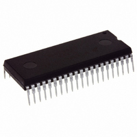
IC MCU 16K FLASH 8MHZ SPI 42SDIP
Manufacturer
Freescale Semiconductor
Series
HC08r
Datasheet
1.MC908GT8CFBE.pdf
(292 pages)
Specifications of MC908GT16CBE
Core Processor
HC08
Core Size
8-Bit
Speed
8MHz
Connectivity
SCI, SPI
Peripherals
LVD, POR, PWM
Number Of I /o
36
Program Memory Size
16KB (16K x 8)
Program Memory Type
FLASH
Ram Size
512 x 8
Voltage - Supply (vcc/vdd)
2.7 V ~ 5.5 V
Data Converters
A/D 8x8b
Oscillator Type
Internal
Operating Temperature
-40°C ~ 85°C
Package / Case
42-DIP (0.600", 15.24mm)
Controller Family/series
HC08
No. Of I/o's
34
Ram Memory Size
512Byte
Cpu Speed
8MHz
No. Of Timers
2
Embedded Interface Type
I2C, SCI, SPI
Rohs Compliant
Yes
Processor Series
HC08GT
Core
HC08
Data Bus Width
8 bit
Data Ram Size
512 B
Interface Type
SCI, SPI
Maximum Clock Frequency
8 MHz
Number Of Programmable I/os
30
Number Of Timers
4
Operating Supply Voltage
0 V to 5 V
Maximum Operating Temperature
+ 85 C
Mounting Style
Through Hole
Development Tools By Supplier
FSICEBASE, DEMO908GZ60E, M68CBL05CE, M68EML08GPGTE
Minimum Operating Temperature
- 40 C
On-chip Adc
8 bit, 8 Channel
Package
42SPDIP
Family Name
HC08
Maximum Speed
8 MHz
Lead Free Status / RoHS Status
Lead free / RoHS Compliant
Eeprom Size
-
Lead Free Status / Rohs Status
Details


Serial Peripheral Interface (SPI) Module
16.3.1 Master Mode
The SPI operates in master mode when the SPI master bit, SPMSTR, is set.
Only a master SPI module can initiate transmissions. Software begins the transmission from a master SPI
module by writing to the transmit data register. If the shift register is empty, the byte immediately transfers
to the shift register, setting the SPI transmitter empty bit, SPTE. The byte begins shifting out on the MOSI
pin under the control of the serial clock. See
The SPR1 and SPR0 bits control the baud rate generator and determine the speed of the shift register.
(See
master also controls the shift register of the slave peripheral.
As the byte shifts out on the MOSI pin of the master, another byte shifts in from the slave on the master’s
MISO pin. The transmission ends when the receiver full bit, SPRF, becomes set. At the same time that
SPRF becomes set, the byte from the slave transfers to the receive data register. In normal operation,
SPRF signals the end of a transmission. Software clears SPRF by reading the SPI status and control
register with SPRF set and then reading the SPI data register. Writing to the SPI data register (SPDR)
clears SPTE.
16.3.2 Slave Mode
The SPI operates in slave mode when SPMSTR is clear. In slave mode, the SPSCK pin is the input for
the serial clock from the master MCU. Before a data transmission occurs, the SS pin of the slave SPI must
be low. SS must remain low until the transmission is complete. See
In a slave SPI module, data enters the shift register under the control of the serial clock from the master
SPI module. After a byte enters the shift register of a slave SPI, it transfers to the receive data register,
and the SPRF bit is set. To prevent an overflow condition, slave software then must read the receive data
register before another full byte enters the shift register.
200
16.12.2 SPI Status and Control
In a multi-SPI system, configure the SPI modules as master or slave before
enabling them. Enable the master SPI before enabling the slave SPI.
Disable the slave SPI before disabling the master SPI. See
Control
SHIFT REGISTER
MC68HC908GT16 • MC68HC908GT8 • MC68HC08GT16 Data Sheet, Rev. 5.0
GENERATOR
MASTER MCU
BAUD RATE
Register.
Figure 16-4. Full-Duplex Master-Slave Connections
Register.) Through the SPSCK pin, the baud rate generator of the
MISO
MOSI
SPSCK
SS
Figure
NOTE
V
16-4.
DD
SPSCK
MISO
MOSI
SS
16.6.2 Mode Fault
SHIFT REGISTER
16.12.1 SPI
SLAVE MCU
Freescale Semiconductor
Error.
Related parts for MC908GT16CBE
Image
Part Number
Description
Manufacturer
Datasheet
Request
R

Part Number:
Description:
Manufacturer:
Freescale Semiconductor, Inc
Datasheet:
Part Number:
Description:
Manufacturer:
Freescale Semiconductor, Inc
Datasheet:
Part Number:
Description:
Manufacturer:
Freescale Semiconductor, Inc
Datasheet:
Part Number:
Description:
Manufacturer:
Freescale Semiconductor, Inc
Datasheet:
Part Number:
Description:
Manufacturer:
Freescale Semiconductor, Inc
Datasheet:
Part Number:
Description:
Manufacturer:
Freescale Semiconductor, Inc
Datasheet:
Part Number:
Description:
Manufacturer:
Freescale Semiconductor, Inc
Datasheet:
Part Number:
Description:
Manufacturer:
Freescale Semiconductor, Inc
Datasheet:
Part Number:
Description:
Manufacturer:
Freescale Semiconductor, Inc
Datasheet:
Part Number:
Description:
Manufacturer:
Freescale Semiconductor, Inc
Datasheet:
Part Number:
Description:
Manufacturer:
Freescale Semiconductor, Inc
Datasheet:
Part Number:
Description:
Manufacturer:
Freescale Semiconductor, Inc
Datasheet:
Part Number:
Description:
Manufacturer:
Freescale Semiconductor, Inc
Datasheet:
Part Number:
Description:
Manufacturer:
Freescale Semiconductor, Inc
Datasheet:
Part Number:
Description:
Manufacturer:
Freescale Semiconductor, Inc
Datasheet: