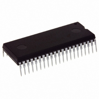
MC908GT16CBE Freescale Semiconductor, MC908GT16CBE Datasheet - Page 194

MC908GT16CBE
Manufacturer Part Number
MC908GT16CBE
Description
IC MCU 16K FLASH 8MHZ SPI 42SDIP
Manufacturer
Freescale Semiconductor
Series
HC08r
Datasheet
1.MC908GT8CFBE.pdf
(292 pages)
Specifications of MC908GT16CBE
Core Processor
HC08
Core Size
8-Bit
Speed
8MHz
Connectivity
SCI, SPI
Peripherals
LVD, POR, PWM
Number Of I /o
36
Program Memory Size
16KB (16K x 8)
Program Memory Type
FLASH
Ram Size
512 x 8
Voltage - Supply (vcc/vdd)
2.7 V ~ 5.5 V
Data Converters
A/D 8x8b
Oscillator Type
Internal
Operating Temperature
-40°C ~ 85°C
Package / Case
42-DIP (0.600", 15.24mm)
Controller Family/series
HC08
No. Of I/o's
34
Ram Memory Size
512Byte
Cpu Speed
8MHz
No. Of Timers
2
Embedded Interface Type
I2C, SCI, SPI
Rohs Compliant
Yes
Processor Series
HC08GT
Core
HC08
Data Bus Width
8 bit
Data Ram Size
512 B
Interface Type
SCI, SPI
Maximum Clock Frequency
8 MHz
Number Of Programmable I/os
30
Number Of Timers
4
Operating Supply Voltage
0 V to 5 V
Maximum Operating Temperature
+ 85 C
Mounting Style
Through Hole
Development Tools By Supplier
FSICEBASE, DEMO908GZ60E, M68CBL05CE, M68EML08GPGTE
Minimum Operating Temperature
- 40 C
On-chip Adc
8 bit, 8 Channel
Package
42SPDIP
Family Name
HC08
Maximum Speed
8 MHz
Lead Free Status / RoHS Status
Lead free / RoHS Compliant
Eeprom Size
-
Lead Free Status / Rohs Status
Details
- Current page: 194 of 292
- Download datasheet (4Mb)
System Integration Module (SIM)
SBSW — SIM Break Stop/Wait
15.7.2 SIM Reset Status Register
The SRSR register contains flags that show the source of the latest reset. The status register will
automatically clear after reading it. A power-on reset sets the POR bit and clears all other bits in the
register. All other reset sources set the individual flag bits but do not clear the register. More than one
reset source can be flagged at any time depending on the conditions at the time of the internal or external
reset. For example, the POR and LVI bits can both be set if the power supply has a slow rise time.
POR — Power-On Reset Bit
PIN — External Reset Bit
COP — Computer Operating Properly Reset Bit
ILOP — Illegal Opcode Reset Bit
ILAD — Illegal Address Reset Bit (opcode fetches only)
MODRST — Monitor Mode Entry Module Reset Bit
LVI — Low-Voltage Inhibit Reset Bit
194
SBSW can be read within the break state SWI routine. The user can modify the return address on the
stack by subtracting one from it.
1 = Wait mode was exited by break interrupt.
0 = Wait mode was not exited by break interrupt.
1 = Last reset caused by POR circuit
0 = Read of SRSR
1 = Last reset caused by external reset pin (RST)
0 = POR or read of SRSR
1 = Last reset caused by COP counter
0 = POR or read of SRSR
1 = Last reset caused by an illegal opcode
0 = POR or read of SRSR
1 = Last reset caused by an opcode fetch from an illegal address
0 = POR or read of SRSR
1 = Last reset caused by monitor mode entry when vector locations $FFFE and $FFFF are $FF after
0 = POR or read of SRSR
1 = Last reset caused by the LVI circuit
0 = POR or read of SRSR
POR while IRQ ≠ V
Address:
Reset:
Read:
Write:
MC68HC908GT16 • MC68HC908GT8 • MC68HC08GT16 Data Sheet, Rev. 5.0
$FE01
POR
Bit 7
1
Figure 15-21. SIM Reset Status Register (SRSR)
TST
= Unimplemented
PIN
6
0
COP
5
0
ILOP
4
0
ILAD
3
0
MODRST
2
0
LVI
1
0
Freescale Semiconductor
Bit 0
0
0
Related parts for MC908GT16CBE
Image
Part Number
Description
Manufacturer
Datasheet
Request
R
Part Number:
Description:
Manufacturer:
Freescale Semiconductor, Inc
Datasheet:
Part Number:
Description:
Manufacturer:
Freescale Semiconductor, Inc
Datasheet:
Part Number:
Description:
Manufacturer:
Freescale Semiconductor, Inc
Datasheet:
Part Number:
Description:
Manufacturer:
Freescale Semiconductor, Inc
Datasheet:
Part Number:
Description:
Manufacturer:
Freescale Semiconductor, Inc
Datasheet:
Part Number:
Description:
Manufacturer:
Freescale Semiconductor, Inc
Datasheet:
Part Number:
Description:
Manufacturer:
Freescale Semiconductor, Inc
Datasheet:
Part Number:
Description:
Manufacturer:
Freescale Semiconductor, Inc
Datasheet:
Part Number:
Description:
Manufacturer:
Freescale Semiconductor, Inc
Datasheet:
Part Number:
Description:
Manufacturer:
Freescale Semiconductor, Inc
Datasheet:
Part Number:
Description:
Manufacturer:
Freescale Semiconductor, Inc
Datasheet:
Part Number:
Description:
Manufacturer:
Freescale Semiconductor, Inc
Datasheet:
Part Number:
Description:
Manufacturer:
Freescale Semiconductor, Inc
Datasheet:
Part Number:
Description:
Manufacturer:
Freescale Semiconductor, Inc
Datasheet:
Part Number:
Description:
Manufacturer:
Freescale Semiconductor, Inc
Datasheet:


