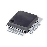
ST7FLITE49K2T6TR STMicroelectronics, ST7FLITE49K2T6TR Datasheet - Page 25

ST7FLITE49K2T6TR
Manufacturer Part Number
ST7FLITE49K2T6TR
Description
IC MCU 8BIT 8K FLASH 32LQFP
Manufacturer
STMicroelectronics
Series
ST7r
Datasheet
1.ST7FLITE49K2T6TR.pdf
(245 pages)
Specifications of ST7FLITE49K2T6TR
Core Processor
ST7
Core Size
8-Bit
Speed
8MHz
Connectivity
I²C, SPI
Peripherals
LVD, POR, PWM, WDT
Number Of I /o
24
Program Memory Size
8KB (8K x 8)
Program Memory Type
FLASH
Eeprom Size
256 x 8
Ram Size
384 x 8
Voltage - Supply (vcc/vdd)
2.4 V ~ 5.5 V
Data Converters
A/D 10x10b
Oscillator Type
Internal
Operating Temperature
-40°C ~ 85°C
Package / Case
32-LQFP
Processor Series
ST7FLITE4x
Core
ST7
Data Bus Width
8 bit
Data Ram Size
384 B
Interface Type
I2C, SPI
Maximum Clock Frequency
8 MHz
Number Of Programmable I/os
24
Number Of Timers
4
Maximum Operating Temperature
+ 85 C
Mounting Style
SMD/SMT
Development Tools By Supplier
ST7FLITE-SK/RAIS, ST7FLI49M-D/RAIS, STX-RLINK
Minimum Operating Temperature
- 40 C
On-chip Adc
10 bit, 10 Channel
For Use With
497-8399 - BOARD EVAL ST7LITE49M/STLED316S497-5858 - EVAL BOARD PLAYBACK ST7FLITE
Lead Free Status / RoHS Status
Lead free / RoHS Compliant
Available stocks
Company
Part Number
Manufacturer
Quantity
Price
Company:
Part Number:
ST7FLITE49K2T6TR
Manufacturer:
STMicroelectronics
Quantity:
10 000
- Current page: 25 of 245
- Download datasheet (4Mb)
ST7LITE49K2
4
4.1
4.2
4.3
4.3.1
Flash programmable memory
Introduction
The ST7 single voltage extended Flash (XFlash) is a non-volatile memory that can be
electrically erased and programmed either on a byte-by-byte basis or up to 32 bytes in
parallel.
The XFlash devices can be programmed off-board (plugged in a programming tool) or on-
board using In-Circuit Programming or In-Application Programming.
The array matrix organization allows each sector to be erased and reprogrammed without
affecting other sectors.
Main features
●
●
●
●
●
Programming modes
The ST7 can be programmed in three different ways:
●
●
●
In-circuit programming (ICP)
ICP uses a protocol called ICC (In-Circuit Communication) which allows an ST7 plugged on
a printed circuit board (PCB) to communicate with an external programming device
connected via cable. ICP is performed in three steps:
Switch the ST7 to ICC mode (In-Circuit Communications). This is done by driving a specific
signal sequence on the ICCCLK/DATA pins while the RESET pin is pulled low. When the
ST7 enters ICC mode, it fetches a specific Reset vector which points to the ST7 System
Memory containing the ICC protocol routine. This routine enables the ST7 to receive bytes
from the ICC interface.
●
●
ICP (In-Circuit Programming)
IAP (In-Application Programming)
ICT (In-Circuit Testing) for downloading and executing user application test patterns in
RAM
Sector 0 size configurable by option byte
Read-out and write protection
Insertion in a programming tool. In this mode, Flash sectors 0 and 1, option byte row
and data EEPROM (if present) can be programmed or erased.
In-Circuit Programming. In this mode, Flash sectors 0 and 1, option byte row and data
EEPROM (if present) can be programmed or erased without removing the device from
the application board.
In-Application Programming. In this mode, sector 1 and data EEPROM (if present) can
be programmed or erased without removing the device from the application board and
while the application is running.
Download ICP Driver code in RAM from the ICCDATA pin
Execute ICP Driver code in RAM to program the Flash memory
Flash programmable memory
25/245
Related parts for ST7FLITE49K2T6TR
Image
Part Number
Description
Manufacturer
Datasheet
Request
R

Part Number:
Description:
STMicroelectronics [RIPPLE-CARRY BINARY COUNTER/DIVIDERS]
Manufacturer:
STMicroelectronics
Datasheet:

Part Number:
Description:
STMicroelectronics [LIQUID-CRYSTAL DISPLAY DRIVERS]
Manufacturer:
STMicroelectronics
Datasheet:

Part Number:
Description:
BOARD EVAL FOR MEMS SENSORS
Manufacturer:
STMicroelectronics
Datasheet:

Part Number:
Description:
NPN TRANSISTOR POWER MODULE
Manufacturer:
STMicroelectronics
Datasheet:

Part Number:
Description:
TURBOSWITCH ULTRA-FAST HIGH VOLTAGE DIODE
Manufacturer:
STMicroelectronics
Datasheet:

Part Number:
Description:
Manufacturer:
STMicroelectronics
Datasheet:

Part Number:
Description:
DIODE / SCR MODULE
Manufacturer:
STMicroelectronics
Datasheet:

Part Number:
Description:
DIODE / SCR MODULE
Manufacturer:
STMicroelectronics
Datasheet:

Part Number:
Description:
Search -----> STE16N100
Manufacturer:
STMicroelectronics
Datasheet:

Part Number:
Description:
Search ---> STE53NA50
Manufacturer:
STMicroelectronics
Datasheet:

Part Number:
Description:
NPN Transistor Power Module
Manufacturer:
STMicroelectronics
Datasheet:

Part Number:
Description:
DIODE / SCR MODULE
Manufacturer:
STMicroelectronics
Datasheet:


