ST7FLITE49K2T6TR STMicroelectronics, ST7FLITE49K2T6TR Datasheet - Page 123
ST7FLITE49K2T6TR
Manufacturer Part Number
ST7FLITE49K2T6TR
Description
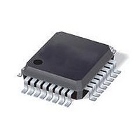
IC MCU 8BIT 8K FLASH 32LQFP
Manufacturer
STMicroelectronics
Series
ST7r
Datasheet
1.ST7FLITE49K2T6TR.pdf
(245 pages)
Specifications of ST7FLITE49K2T6TR
Core Processor
ST7
Core Size
8-Bit
Speed
8MHz
Connectivity
I²C, SPI
Peripherals
LVD, POR, PWM, WDT
Number Of I /o
24
Program Memory Size
8KB (8K x 8)
Program Memory Type
FLASH
Eeprom Size
256 x 8
Ram Size
384 x 8
Voltage - Supply (vcc/vdd)
2.4 V ~ 5.5 V
Data Converters
A/D 10x10b
Oscillator Type
Internal
Operating Temperature
-40°C ~ 85°C
Package / Case
32-LQFP
Processor Series
ST7FLITE4x
Core
ST7
Data Bus Width
8 bit
Data Ram Size
384 B
Interface Type
I2C, SPI
Maximum Clock Frequency
8 MHz
Number Of Programmable I/os
24
Number Of Timers
4
Maximum Operating Temperature
+ 85 C
Mounting Style
SMD/SMT
Development Tools By Supplier
ST7FLITE-SK/RAIS, ST7FLI49M-D/RAIS, STX-RLINK
Minimum Operating Temperature
- 40 C
On-chip Adc
10 bit, 10 Channel
For Use With
497-8399 - BOARD EVAL ST7LITE49M/STLED316S497-5858 - EVAL BOARD PLAYBACK ST7FLITE
Lead Free Status / RoHS Status
Lead free / RoHS Compliant
Available stocks
Company
Part Number
Manufacturer
Quantity
Price
Company:

Part Number:
ST7FLITE49K2T6TR
Manufacturer:
STMicroelectronics
Quantity:
10 000


ST7LITE49K2
Note:
1
2
3
4
5
The OC
the following formula:
Equation 1
Where:
Δ
f
PRESC
If the timer clock is an external clock, the formula is:
Equation 2
Where:
Δ
f
Clearing the output compare interrupt request (that is, clearing the OCFi bit) is done by:
1.
2.
The following procedure is recommended to prevent the OCFi bit from being set between
the time it is read and the time it is written to the OC
●
●
●
After a processor write cycle to the OCiHR register, the output compare function is inhibited
until the OCiLR register is also written.
If the OCiE bit is not set, the OCMPi pin is a general I/O port and the OLVLi bit does not
appear when a match is found but an interrupt could be generated if the OCIE bit is set.
In both internal and external clock modes, OCFi and OCMPi are set while the counter value
equals the OCiR register value (see
an example with f
The output compare functions can be used both for generating external events on the
OCMPi pins even if the input capture mode is also used.
The value in the 16-bit OC
successful comparison in order to control an output waveform or establish a new elapsed
timeout.
CPU
EXT
t =
t =
=
Reading the SR register while the OCFi bit is set.
Accessing (reading or writing) the OCiLR register.
Write to the OCiHR register (further compares are inhibited).
Read the SR register (first step in the clearance of the OCFi bit, which may be already
set).
Write to the OCiLR register (enables the output compare function and clears the OCFi
bit).
=
=
i
R register value required for a specific timing application can be calculated using
Δ
output compare period (in seconds)
CPU clock frequency (in hertz)
timer prescaler factor (2, 4 or 8 depending on CC[1:0] bits, see
register 2 (TACR2) on page
output compare period (in seconds)
external timer clock frequency (in hertz)
OCiR =
CPU
Δt
/4). This behavior is the same in OPM or PWM mode.
*
f
EXT
i
R register and the OLVi bit should be changed after each
Δ
Figure 63
OCiR =
132)
for an example with f
Δt
PRESC
*
f
CPU
i
R register:
CPU
On-chip peripherals
/2 and
: Timer A control
Figure 64
123/245
for
Related parts for ST7FLITE49K2T6TR
Image
Part Number
Description
Manufacturer
Datasheet
Request
R

Part Number:
Description:
STMicroelectronics [RIPPLE-CARRY BINARY COUNTER/DIVIDERS]
Manufacturer:
STMicroelectronics
Datasheet:
Part Number:
Description:
STMicroelectronics [LIQUID-CRYSTAL DISPLAY DRIVERS]
Manufacturer:
STMicroelectronics
Datasheet:

Part Number:
Description:
BOARD EVAL FOR MEMS SENSORS
Manufacturer:
STMicroelectronics
Datasheet:
Part Number:
Description:
NPN TRANSISTOR POWER MODULE
Manufacturer:
STMicroelectronics
Datasheet:
Part Number:
Description:
TURBOSWITCH ULTRA-FAST HIGH VOLTAGE DIODE
Manufacturer:
STMicroelectronics
Datasheet:
Part Number:
Description:
Manufacturer:
STMicroelectronics
Datasheet:
Part Number:
Description:
DIODE / SCR MODULE
Manufacturer:
STMicroelectronics
Datasheet:
Part Number:
Description:
DIODE / SCR MODULE
Manufacturer:
STMicroelectronics
Datasheet:
Part Number:
Description:
Search -----> STE16N100
Manufacturer:
STMicroelectronics
Datasheet:
Part Number:
Description:
Search ---> STE53NA50
Manufacturer:
STMicroelectronics
Datasheet:
Part Number:
Description:
NPN Transistor Power Module
Manufacturer:
STMicroelectronics
Datasheet:
Part Number:
Description:
DIODE / SCR MODULE
Manufacturer:
STMicroelectronics
Datasheet: