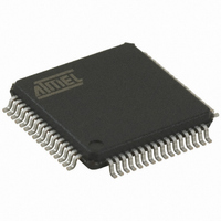
AT32UC3B0512-A2UT Atmel, AT32UC3B0512-A2UT Datasheet - Page 373

AT32UC3B0512-A2UT
Manufacturer Part Number
AT32UC3B0512-A2UT
Description
IC MCU AVR32 512K FLASH 64TQFP
Manufacturer
Atmel
Series
AVR®32 UC3r
Specifications of AT32UC3B0512-A2UT
Core Processor
AVR
Core Size
32-Bit
Speed
60MHz
Connectivity
I²C, IrDA, SPI, SSC, UART/USART, USB
Peripherals
Brown-out Detect/Reset, DMA, POR, PWM, WDT
Number Of I /o
44
Program Memory Size
512KB (512K x 8)
Program Memory Type
FLASH
Ram Size
96K x 8
Voltage - Supply (vcc/vdd)
1.65 V ~ 1.95 V
Data Converters
A/D 8x10b
Oscillator Type
Internal
Operating Temperature
-40°C ~ 85°C
Package / Case
64-TQFP, 64-VQFP
Controller Family/series
AT32UC3B
No. Of I/o's
44
Ram Memory Size
96KB
Cpu Speed
60MHz
No. Of Timers
1
Rohs Compliant
Yes
Lead Free Status / RoHS Status
Lead free / RoHS Compliant
Eeprom Size
-
Available stocks
Company
Part Number
Manufacturer
Quantity
Price
Company:
Part Number:
AT32UC3B0512-A2UT
Manufacturer:
MURATA
Quantity:
11 450
Part Number:
AT32UC3B0512-A2UT
Manufacturer:
ATMEL/爱特梅尔
Quantity:
20 000
- Current page: 373 of 692
- Download datasheet (11Mb)
22.7.1.5
22.7.1.6
32059K–03/2011
Speed control
DPRAM management
•USB Suspend mode
•Device mode
•Host mode
Moreover, when FRZCLK is written to one, only the asynchronous interrupt sources may trigger
the USB interrupt:
In peripheral mode, the Suspend Interrupt bit in the Device Global Interrupt register
(UDINT.SUSP)indicates that the USB line is in the suspend mode. In this case, the USB Data
UTMI transceiver is automatically set in suspend mode to reduce the consumption.
When the USBB interface is in device mode, the speed selection (full-/low-speed) depends on
which of D+ and D- is pulled up. The LS bit allows to connect an internal pull-up resistor either
on D+ (full-speed mode) or on D- (low-speed mode). The LS bit shall be written before attaching
the device, what can be done by clearing the DETACH bit in UDCON.
Figure 22-7. Speed Selection in Device Mode
When the USB interface is in host mode, internal pull-down resistors are connected on both D+
and D- and the interface detects the speed of the connected device, which is reflected by the
Speed Status (SPEED) field in USBSTA.
Pipes and endpoints can only be allocated in ascending order (from the pipe/endpoint 0 to the
last pipe/endpoint to be allocated). The user shall therefore configure them in the same order.
The allocation of a pipe/endpoint n starts when the Endpoint Memory Allocate bit in the Endpoint
n Configuration register (UECFGn.ALLOC) is written to one. Then, the hardware allocates a
• The ID Transition Interrupt (IDTI)
• The VBus Transition Interrupt (VBUSTI)
• The Wake-up Interrupt (WAKEUP)
• The Host Wake-up Interrupt (HWUPI)
VBUS
D+
D-
UDCON.DETACH
UDCON.LS
AT32UC3B
373
Related parts for AT32UC3B0512-A2UT
Image
Part Number
Description
Manufacturer
Datasheet
Request
R

Part Number:
Description:
DEV KIT FOR AVR/AVR32
Manufacturer:
Atmel
Datasheet:

Part Number:
Description:
INTERVAL AND WIPE/WASH WIPER CONTROL IC WITH DELAY
Manufacturer:
ATMEL Corporation
Datasheet:

Part Number:
Description:
Low-Voltage Voice-Switched IC for Hands-Free Operation
Manufacturer:
ATMEL Corporation
Datasheet:

Part Number:
Description:
MONOLITHIC INTEGRATED FEATUREPHONE CIRCUIT
Manufacturer:
ATMEL Corporation
Datasheet:

Part Number:
Description:
AM-FM Receiver IC U4255BM-M
Manufacturer:
ATMEL Corporation
Datasheet:

Part Number:
Description:
Monolithic Integrated Feature Phone Circuit
Manufacturer:
ATMEL Corporation
Datasheet:

Part Number:
Description:
Multistandard Video-IF and Quasi Parallel Sound Processing
Manufacturer:
ATMEL Corporation
Datasheet:

Part Number:
Description:
High-performance EE PLD
Manufacturer:
ATMEL Corporation
Datasheet:

Part Number:
Description:
8-bit Flash Microcontroller
Manufacturer:
ATMEL Corporation
Datasheet:

Part Number:
Description:
2-Wire Serial EEPROM
Manufacturer:
ATMEL Corporation
Datasheet:


