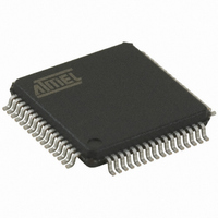
AT32UC3B0512-A2UT Atmel, AT32UC3B0512-A2UT Datasheet - Page 103

AT32UC3B0512-A2UT
Manufacturer Part Number
AT32UC3B0512-A2UT
Description
IC MCU AVR32 512K FLASH 64TQFP
Manufacturer
Atmel
Series
AVR®32 UC3r
Specifications of AT32UC3B0512-A2UT
Core Processor
AVR
Core Size
32-Bit
Speed
60MHz
Connectivity
I²C, IrDA, SPI, SSC, UART/USART, USB
Peripherals
Brown-out Detect/Reset, DMA, POR, PWM, WDT
Number Of I /o
44
Program Memory Size
512KB (512K x 8)
Program Memory Type
FLASH
Ram Size
96K x 8
Voltage - Supply (vcc/vdd)
1.65 V ~ 1.95 V
Data Converters
A/D 8x10b
Oscillator Type
Internal
Operating Temperature
-40°C ~ 85°C
Package / Case
64-TQFP, 64-VQFP
Controller Family/series
AT32UC3B
No. Of I/o's
44
Ram Memory Size
96KB
Cpu Speed
60MHz
No. Of Timers
1
Rohs Compliant
Yes
Lead Free Status / RoHS Status
Lead free / RoHS Compliant
Eeprom Size
-
Available stocks
Company
Part Number
Manufacturer
Quantity
Price
Company:
Part Number:
AT32UC3B0512-A2UT
Manufacturer:
MURATA
Quantity:
11 450
Part Number:
AT32UC3B0512-A2UT
Manufacturer:
ATMEL/爱特梅尔
Quantity:
20 000
- Current page: 103 of 692
- Download datasheet (11Mb)
13.6.6
32059K–03/2011
Keypad scan support
The External Interrupt Controller also includes support for keypad scanning. The keypad scan
feature is compatible with keypads organized as rows and columns, where a row is shorted
against a column when a key is pressed.
The rows should be connected to the external interrupt pins with pull-ups enabled in the I/O Con-
troller. These external interrupts should be enabled as low level or falling edge interrupts. The
columns should be connected to the available scan pins. The I/O Controller must be configured
to let the required scan pins be controlled by the EIC. Unused external interrupt or scan pins can
be left controlled by the I/O Controller or other peripherals.
The Keypad Scan function is enabled by writing SCAN.EN to 1, which starts the keypad scan
counter. The SCAN outputs are tri-stated, except SCAN[0], which is driven to zero. After
2
the other outputs are tri-stated. This sequence repeats infinitely, wrapping from the most signifi-
cant SCAN pin to SCAN[0].
When a key is pressed, the pulled-up row is driven to zero by the column, and an external inter-
rupt triggers. The scanning stops, and the software can then identify the key pressed by the
interrupt status register and the SCAN.PINS value.
The scanning stops whenever there is an active interrupt request from the EIC to the CPU.
When the CPU clears the interrupt flags, scanning resumes.
(SCAN.PRESC+1)
RC clock cycles this pattern is left shifted, so that SCAN[1] is driven to zero while
AT32UC3B
103
Related parts for AT32UC3B0512-A2UT
Image
Part Number
Description
Manufacturer
Datasheet
Request
R

Part Number:
Description:
DEV KIT FOR AVR/AVR32
Manufacturer:
Atmel
Datasheet:

Part Number:
Description:
INTERVAL AND WIPE/WASH WIPER CONTROL IC WITH DELAY
Manufacturer:
ATMEL Corporation
Datasheet:

Part Number:
Description:
Low-Voltage Voice-Switched IC for Hands-Free Operation
Manufacturer:
ATMEL Corporation
Datasheet:

Part Number:
Description:
MONOLITHIC INTEGRATED FEATUREPHONE CIRCUIT
Manufacturer:
ATMEL Corporation
Datasheet:

Part Number:
Description:
AM-FM Receiver IC U4255BM-M
Manufacturer:
ATMEL Corporation
Datasheet:

Part Number:
Description:
Monolithic Integrated Feature Phone Circuit
Manufacturer:
ATMEL Corporation
Datasheet:

Part Number:
Description:
Multistandard Video-IF and Quasi Parallel Sound Processing
Manufacturer:
ATMEL Corporation
Datasheet:

Part Number:
Description:
High-performance EE PLD
Manufacturer:
ATMEL Corporation
Datasheet:

Part Number:
Description:
8-bit Flash Microcontroller
Manufacturer:
ATMEL Corporation
Datasheet:

Part Number:
Description:
2-Wire Serial EEPROM
Manufacturer:
ATMEL Corporation
Datasheet:


