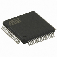
AT32UC3B0512-A2UT Atmel, AT32UC3B0512-A2UT Datasheet - Page 191

AT32UC3B0512-A2UT
Manufacturer Part Number
AT32UC3B0512-A2UT
Description
IC MCU AVR32 512K FLASH 64TQFP
Manufacturer
Atmel
Series
AVR®32 UC3r
Specifications of AT32UC3B0512-A2UT
Core Processor
AVR
Core Size
32-Bit
Speed
60MHz
Connectivity
I²C, IrDA, SPI, SSC, UART/USART, USB
Peripherals
Brown-out Detect/Reset, DMA, POR, PWM, WDT
Number Of I /o
44
Program Memory Size
512KB (512K x 8)
Program Memory Type
FLASH
Ram Size
96K x 8
Voltage - Supply (vcc/vdd)
1.65 V ~ 1.95 V
Data Converters
A/D 8x10b
Oscillator Type
Internal
Operating Temperature
-40°C ~ 85°C
Package / Case
64-TQFP, 64-VQFP
Controller Family/series
AT32UC3B
No. Of I/o's
44
Ram Memory Size
96KB
Cpu Speed
60MHz
No. Of Timers
1
Rohs Compliant
Yes
Lead Free Status / RoHS Status
Lead free / RoHS Compliant
Eeprom Size
-
Available stocks
Company
Part Number
Manufacturer
Quantity
Price
Company:
Part Number:
AT32UC3B0512-A2UT
Manufacturer:
MURATA
Quantity:
11 450
Part Number:
AT32UC3B0512-A2UT
Manufacturer:
ATMEL/爱特梅尔
Quantity:
20 000
- Current page: 191 of 692
- Download datasheet (11Mb)
17.7
17.7.1
17.7.2
32059K–03/2011
Programming Examples
8-bit LED-Chaser
Configuration of USART pins
It is assumed in this example that a subroutine "delay" exists that returns after a given time.
The example below shows how to configure a peripheral module to control I/O pins. It assumed
in this example that the USART receive pin (RXD) is connected to PC16 and that the USART
transmit pin (TXD) is connected to PC17. For both pins, the USART is peripheral B. In this
example, the state of the GPIO registers is assumed to be unknown. The two USART pins are
therefore first set to be controlled by the GPIO with output drivers disabled. The pins can then be
assured to be tri-stated while changing the Peripheral Mux Registers.
loop:
// Set R0 to GPIO base address
mov
orh
// Enable GPIO control of pin 0-8
mov
st.w
// Set initial value of port
mov
st.w
// Set up toggle value. Two pins are toggled
// in each round. The bit that is currently set,
// and the next bit to be set.
mov
orh
// Only change 8 LSB
mov
and
st.w
rol
rcall
rjmp
// Set up pointer to GPIO, PORTC
mov
orh
// Disable output drivers
R0, LO(AVR32_GPIO_ADDRESS)
R0, HI(AVR32_GPIO_ADDRESS)
R1, 0xFF
R0[AVR32_GPIO_GPERS], R1
R2, 0x01
R0[AVR32_GPIO_OVRS], R2
R2, 0x0303
R2, 0x0303
R3, 0x00FF
R3, R2
R0[AVR32_GPIO_OVRT], R3
R2
delay
loop
R0, LO(AVR32_GPIO_ADDRESS + PORTC_OFFSET)
R0, HI(AVR32_GPIO_ADDRESS + PORTC_OFFSET)
AT32UC3B
191
Related parts for AT32UC3B0512-A2UT
Image
Part Number
Description
Manufacturer
Datasheet
Request
R

Part Number:
Description:
DEV KIT FOR AVR/AVR32
Manufacturer:
Atmel
Datasheet:

Part Number:
Description:
INTERVAL AND WIPE/WASH WIPER CONTROL IC WITH DELAY
Manufacturer:
ATMEL Corporation
Datasheet:

Part Number:
Description:
Low-Voltage Voice-Switched IC for Hands-Free Operation
Manufacturer:
ATMEL Corporation
Datasheet:

Part Number:
Description:
MONOLITHIC INTEGRATED FEATUREPHONE CIRCUIT
Manufacturer:
ATMEL Corporation
Datasheet:

Part Number:
Description:
AM-FM Receiver IC U4255BM-M
Manufacturer:
ATMEL Corporation
Datasheet:

Part Number:
Description:
Monolithic Integrated Feature Phone Circuit
Manufacturer:
ATMEL Corporation
Datasheet:

Part Number:
Description:
Multistandard Video-IF and Quasi Parallel Sound Processing
Manufacturer:
ATMEL Corporation
Datasheet:

Part Number:
Description:
High-performance EE PLD
Manufacturer:
ATMEL Corporation
Datasheet:

Part Number:
Description:
8-bit Flash Microcontroller
Manufacturer:
ATMEL Corporation
Datasheet:

Part Number:
Description:
2-Wire Serial EEPROM
Manufacturer:
ATMEL Corporation
Datasheet:


