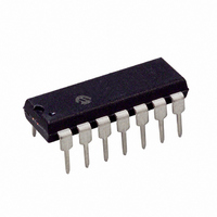
PIC16F526-I/P Microchip Technology, PIC16F526-I/P Datasheet - Page 47

PIC16F526-I/P
Manufacturer Part Number
PIC16F526-I/P
Description
IC PIC MCU FLASH 1KX12 14DIP
Manufacturer
Microchip Technology
Series
PIC® 16Fr
Datasheets
1.PIC16F526-ISL.pdf
(122 pages)
2.PIC16F526-ISL.pdf
(22 pages)
3.PIC16F526-IP.pdf
(104 pages)
Specifications of PIC16F526-I/P
Program Memory Type
FLASH
Program Memory Size
1.5KB (1K x 12)
Package / Case
14-DIP (0.300", 7.62mm)
Core Processor
PIC
Core Size
8-Bit
Speed
20MHz
Peripherals
POR, WDT
Number Of I /o
11
Ram Size
67 x 8
Voltage - Supply (vcc/vdd)
2 V ~ 5.5 V
Data Converters
A/D 3x8b
Oscillator Type
Internal
Operating Temperature
-40°C ~ 85°C
Processor Series
PIC16F
Core
PIC
Data Bus Width
8 bit
Data Ram Size
67 B
Maximum Clock Frequency
20 MHz
Number Of Programmable I/os
12
Number Of Timers
1
Maximum Operating Temperature
+ 85 C
Mounting Style
Through Hole
3rd Party Development Tools
52715-96, 52716-328, 52717-734
Development Tools By Supplier
PG164130, DV164035, DV244005, DV164005, PG164120, ICE2000
Minimum Operating Temperature
- 40 C
On-chip Adc
8 bit, 3 Channel
Lead Free Status / RoHS Status
Lead free / RoHS Compliant
For Use With
AC162096 - HEADER MPLAB ICD2 PIC16F526 8/14
Eeprom Size
-
Connectivity
-
Lead Free Status / Rohs Status
Lead free / RoHS Compliant
Also, see the Electrical Specifications section for
variation of oscillator frequency due to V
R
to operating temperature for given R, C and V
values.
FIGURE 8-5:
2010 Microchip Technology Inc.
EXT
C
V
R
SS
EXT
EXT
/C
F
V
OSC
EXT
DD
/4
values, as well as frequency variation due
EXTERNAL RC
OSCILLATOR MODE
OSC1
OSC2/CLKOUT
N
PIC16F526
DD
Internal
clock
for given
DD
8.2.5
The internal RC oscillator provides a fixed 4/8 MHz
(nominal) system clock at V
Section 14.0
information on variation over voltage and temperature).
In addition, a calibration instruction is programmed into
the last address of memory, which contains the calibra-
tion value for the internal RC oscillator. This location is
always non-code protected, regardless of the code-
protect settings. This value is programmed as a MOVLW
XX instruction where XX is the calibration value, and is
placed at the Reset vector. This will load the W register
with the calibration value upon Reset and the PC will
then roll over to the users program at address 0x000.
The user then has the option of writing the value to the
OSCCAL Register (05h) or ignoring it.
OSCCAL, when written to with the calibration value, will
“trim” the internal oscillator to remove process variation
from the oscillator frequency.
For the PIC16F526 device, only bits 7:1 of OSCCAL
are used for calibration. See Register 4-3 for more
information.
Note:
Note:
INTERNAL 4/8 MHz RC
OSCILLATOR
Erasing the device will also erase the pre-
programmed internal calibration value for
the internal oscillator. The calibration
value must be read prior to erasing the
part so it can be reprogrammed correctly
later.
The bit 0 of the OSCCAL register is
unimplemented and should be written as
‘0’
compatibility with future devices.
“Electrical
when
modifying
PIC16F526
DD
Characteristics”
= 5V and 25°C, (see
DS41326E-page 47
OSCCAL
for
for


