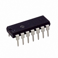
PIC16F526-I/P Microchip Technology, PIC16F526-I/P Datasheet - Page 45

PIC16F526-I/P
Manufacturer Part Number
PIC16F526-I/P
Description
IC PIC MCU FLASH 1KX12 14DIP
Manufacturer
Microchip Technology
Series
PIC® 16Fr
Datasheets
1.PIC16F526-ISL.pdf
(122 pages)
2.PIC16F526-ISL.pdf
(22 pages)
3.PIC16F526-IP.pdf
(104 pages)
Specifications of PIC16F526-I/P
Program Memory Type
FLASH
Program Memory Size
1.5KB (1K x 12)
Package / Case
14-DIP (0.300", 7.62mm)
Core Processor
PIC
Core Size
8-Bit
Speed
20MHz
Peripherals
POR, WDT
Number Of I /o
11
Ram Size
67 x 8
Voltage - Supply (vcc/vdd)
2 V ~ 5.5 V
Data Converters
A/D 3x8b
Oscillator Type
Internal
Operating Temperature
-40°C ~ 85°C
Processor Series
PIC16F
Core
PIC
Data Bus Width
8 bit
Data Ram Size
67 B
Maximum Clock Frequency
20 MHz
Number Of Programmable I/os
12
Number Of Timers
1
Maximum Operating Temperature
+ 85 C
Mounting Style
Through Hole
3rd Party Development Tools
52715-96, 52716-328, 52717-734
Development Tools By Supplier
PG164130, DV164035, DV244005, DV164005, PG164120, ICE2000
Minimum Operating Temperature
- 40 C
On-chip Adc
8 bit, 3 Channel
Lead Free Status / RoHS Status
Lead free / RoHS Compliant
For Use With
AC162096 - HEADER MPLAB ICD2 PIC16F526 8/14
Eeprom Size
-
Connectivity
-
Lead Free Status / Rohs Status
Lead free / RoHS Compliant
8.2
8.2.1
The PIC16F526 device can be operated in up to six
different oscillator modes. The user can program up to
three Configuration bits (FOSC<2:0>). To select one of
these modes:
• LP:
• XT:
• HS:
• INTRC: Internal 4/8 MHz Oscillator
• EXTRC: External Resistor/Capacitor
• EC:
8.2.2
In HS, XT or LP modes, a crystal or ceramic resonator
is connected to the RB5/OSC1/CLKIN and RB4/OSC2/
CLKOUT pins to establish oscillation (Figure 8-1). The
PIC16F526 oscillator designs require the use of a
parallel cut crystal. Use of a series cut crystal may give
a frequency out of the crystal manufacturers
specifications. When in HS, XT or LP modes, the
device can have an external clock source drive the
RB5/OSC1/CLKIN pin (Figure 8-2). In this mode, the
output drive levels on the OSC2 pin are very weak. If
the part is used in this fashion, then this pin should be
left open and unloaded. Also when using this mode, the
external clock should observe the frequency limits for
the Clock mode chosen (HS, XT or LP).
2010 Microchip Technology Inc.
Note 1: This device has been designed to per-
2: The user should verify that the device
Oscillator Configurations
Low-Power Crystal
Crystal/Resonator
High-Speed Crystal/Resonator
External High-Speed Clock Input
CRYSTAL OSCILLATOR/CERAMIC
RESONATORS
OSCILLATOR TYPES
form to the parameters of its data sheet.
It has been tested to an electrical
specification designed to determine its
conformance with these parameters.
Due to process differences in the
manufacture of this device, this device
may have different performance charac-
teristics than its earlier version. These
differences may cause this device to
perform differently in your application
than the earlier version of this device.
oscillator
expected. Adjusting the loading capacitor
values and/or the Oscillator mode may
be required.
starts
and
performs
as
FIGURE 8-1:
FIGURE 8-2:
TABLE 8-1:
Note 1:
OSC2/CLKOUT/RB4
EC, HS, XT, LP
Note 1:
Note 1: RB4 is available in EC mode only.
Type
Osc
Clock From
ext. system
XT
HS
C2
C1
2:
3:
(1)
(1)
Resonator
These values are for design guidance
only. Since each resonator has its own
characteristics, the user should consult
the resonator manufacturer for
appropriate values of external
components.
4.0 MHz
See Capacitor Selection tables for
recommended values of C1 and C2.
A series resistor (RS) may be required for AT
strip cut crystals.
RF approx. value = 10 M.
16 MHz
Freq.
RS
XTAL
(2)
CAPACITOR SELECTION FOR
CERAMIC RESONATORS
OSC2
OSC1
CRYSTAL OPERATION
(OR CERAMIC
RESONATOR)
(HS, XT OR LP OSC
CONFIGURATION)
EXTERNAL CLOCK INPUT
OPERATION (HS, XT, LP
OR EC OSC
CONFIGURATION)
Cap. Range
PIC16F526
10-47 pF
OSC2/CLKOUT/RB4
RB5/OSC1/CLKIN
30 pF
C1
RF
(3)
PIC16F526
DS41326E-page 45
PIC16F526
Cap. Range
10-47 pF
To internal
Sleep
30 pF
C2
logic
(1)


