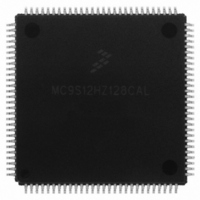
MC9S12HZ128CAL Freescale Semiconductor, MC9S12HZ128CAL Datasheet - Page 338

MC9S12HZ128CAL
Manufacturer Part Number
MC9S12HZ128CAL
Description
IC MCU 16BIT 128K FLASH 112-LQFP
Manufacturer
Freescale Semiconductor
Series
HCS12r
Datasheet
1.MC9S12HZ128CAL.pdf
(692 pages)
Specifications of MC9S12HZ128CAL
Core Processor
HCS12
Core Size
16-Bit
Speed
25MHz
Connectivity
CAN, EBI/EMI, I²C, SCI, SPI
Peripherals
LCD, Motor control PWM, POR, PWM, WDT
Number Of I /o
85
Program Memory Size
128KB (128K x 8)
Program Memory Type
FLASH
Eeprom Size
2K x 8
Ram Size
6K x 8
Voltage - Supply (vcc/vdd)
2.35 V ~ 5.5 V
Data Converters
A/D 16x10b
Oscillator Type
Internal
Operating Temperature
-40°C ~ 85°C
Package / Case
112-LQFP
Processor Series
S12H
Core
HCS12
Data Bus Width
16 bit
Data Ram Size
6 KB
Interface Type
I2C, SCI, SPI
Maximum Clock Frequency
50 MHz
Number Of Programmable I/os
85
Number Of Timers
8
Maximum Operating Temperature
+ 85 C
Mounting Style
SMD/SMT
3rd Party Development Tools
EWHCS12
Minimum Operating Temperature
- 40 C
On-chip Adc
10 bit, 16 Channel
Lead Free Status / RoHS Status
Lead free / RoHS Compliant
Available stocks
Company
Part Number
Manufacturer
Quantity
Price
Company:
Part Number:
MC9S12HZ128CAL
Manufacturer:
Freescale Semiconductor
Quantity:
10 000
- Current page: 338 of 692
- Download datasheet (4Mb)
Chapter 12 Freescale’s Scalable Controller Area Network (MSCANV2)
12.3.2
This section describes in detail all the registers and register bits in the MSCAN module. Each description
includes a standard register diagram with an associated figure number. Details of register bit and field
function follow the register diagrams, in bit order. All bits of all registers in this module are completely
synchronous to internal clocks during a register read.
12.3.2.1
The CANCTL0 register provides various control bits of the MSCAN module as described below.
Read: Anytime
Write: Anytime when out of initialization mode; exceptions are read-only RXACT and SYNCH, RXFRM
(which is set by the module only), and INITRQ (which is also writable in initialization mode).
338
RXFRM
CSWAI
RXACT
Field
7
6
5
Reset:
3
1
W
R
2
Register Descriptions
Reserved bits and unused bits within the TX- and RX-buffers (CANTXFG, CANRXFG) will be read
as “x”, because of RAM-based implementation.
Received Frame Flag — This bit is read and clear only. It is set when a receiver has received a valid message
correctly, independently of the filter configuration. After it is set, it remains set until cleared by software or reset.
Clearing is done by writing a 1. Writing a 0 is ignored. This bit is not valid in loopback mode.
0 No valid message was received since last clearing this flag
1 A valid message was received since last clearing of this flag
Receiver Active Status — This read-only flag indicates the MSCAN is receiving a message. The flag is
controlled by the receiver front end. This bit is not valid in loopback mode.
0 MSCAN is transmitting or idle
1 MSCAN is receiving a message (including when arbitration is lost)
CAN Stops in Wait Mode — Enabling this bit allows for lower power consumption in wait mode by disabling all
the clocks at the CPU bus interface to the MSCAN module.
0 The module is not affected during wait mode
1 The module ceases to be clocked during wait mode
MSCAN Control Register 0 (CANCTL0)
RXFRM
The CANCTL0 register, except WUPE, INITRQ, and SLPRQ, is held in the
reset state when the initialization mode is active (INITRQ = 1 and
INITAK = 1). This register is writable again as soon as the initialization
mode is exited (INITRQ = 0 and INITAK = 0).
0
7
= Unimplemented
RXACT
Figure 12-3. MSCAN Control Register 0 (CANCTL0)
Table 12-3. CANCTL0 Register Field Descriptions
6
0
MC9S12HZ256 Data Sheet, Rev. 2.05
CSWAI
2
0
5
NOTE
SYNCH
4
0
Description
TIME
0
3
2
WUPE
2
0
Freescale Semiconductor
SLPRQ
0
1
INITRQ
0
1
Related parts for MC9S12HZ128CAL
Image
Part Number
Description
Manufacturer
Datasheet
Request
R
Part Number:
Description:
Manufacturer:
Freescale Semiconductor, Inc
Datasheet:
Part Number:
Description:
Manufacturer:
Freescale Semiconductor, Inc
Datasheet:
Part Number:
Description:
Manufacturer:
Freescale Semiconductor, Inc
Datasheet:
Part Number:
Description:
Manufacturer:
Freescale Semiconductor, Inc
Datasheet:
Part Number:
Description:
Manufacturer:
Freescale Semiconductor, Inc
Datasheet:
Part Number:
Description:
Manufacturer:
Freescale Semiconductor, Inc
Datasheet:
Part Number:
Description:
Manufacturer:
Freescale Semiconductor, Inc
Datasheet:
Part Number:
Description:
Manufacturer:
Freescale Semiconductor, Inc
Datasheet:
Part Number:
Description:
Manufacturer:
Freescale Semiconductor, Inc
Datasheet:
Part Number:
Description:
Manufacturer:
Freescale Semiconductor, Inc
Datasheet:
Part Number:
Description:
Manufacturer:
Freescale Semiconductor, Inc
Datasheet:
Part Number:
Description:
Manufacturer:
Freescale Semiconductor, Inc
Datasheet:
Part Number:
Description:
Manufacturer:
Freescale Semiconductor, Inc
Datasheet:
Part Number:
Description:
Manufacturer:
Freescale Semiconductor, Inc
Datasheet:
Part Number:
Description:
Manufacturer:
Freescale Semiconductor, Inc
Datasheet:


