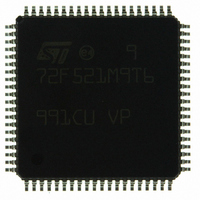
ST72F521M9T6 STMicroelectronics, ST72F521M9T6 Datasheet - Page 43

ST72F521M9T6
Manufacturer Part Number
ST72F521M9T6
Description
IC MCU 8BIT 60K FLASH 80-TQFP
Manufacturer
STMicroelectronics
Series
ST7r
Datasheet
1.ST72F521M9T6.pdf
(215 pages)
Specifications of ST72F521M9T6
Core Processor
ST7
Core Size
8-Bit
Speed
8MHz
Connectivity
CAN, LINSCI, SPI
Peripherals
LVD, POR, PWM, WDT
Number Of I /o
64
Program Memory Size
60KB (60K x 8)
Program Memory Type
FLASH
Ram Size
2K x 8
Voltage - Supply (vcc/vdd)
3.8 V ~ 5.5 V
Data Converters
A/D 16x10b
Oscillator Type
Internal
Operating Temperature
-40°C ~ 85°C
Package / Case
80-TQFP, 80-VQFP
Processor Series
ST72F5x
Core
ST7
Data Bus Width
8 bit
Data Ram Size
2048 B
Interface Type
CAN, I2C, SCI, SPI
Maximum Clock Frequency
8 MHz
Number Of Programmable I/os
64
Number Of Timers
5
Operating Supply Voltage
3.8 V to 5.5 V
Maximum Operating Temperature
+ 85 C
Mounting Style
SMD/SMT
Minimum Operating Temperature
- 40 C
On-chip Adc
10 bit
For Use With
497-6453 - BOARD EVAL BASED ON ST7LNBX497-5046 - KIT TOOL FOR ST7/UPSD/STR7 MCU
Lead Free Status / RoHS Status
Lead free / RoHS Compliant
Eeprom Size
-
Lead Free Status / Rohs Status
Details
Other names
497-8244
ST72F521M9T6
ST72F521M9T6
Available stocks
Company
Part Number
Manufacturer
Quantity
Price
Company:
Part Number:
ST72F521M9T6
Manufacturer:
ST
Quantity:
37 800
Company:
Part Number:
ST72F521M9T6
Manufacturer:
STMicroelectronics
Quantity:
10 000
Company:
Part Number:
ST72F521M9T6TR
Manufacturer:
STMicroelectronics
Quantity:
10 000
POWER SAVING MODES (Cont’d)
8.3 WAIT MODE
WAIT mode places the MCU in a low power con-
sumption mode by stopping the CPU.
This power saving mode is selected by calling the
‘WFI’ instruction.
All peripherals remain active. During WAIT mode,
the I[1:0] bits of the CC register are forced to ‘10’,
to enable all interrupts. All other registers and
memory remain unchanged. The MCU remains in
WAIT mode until an interrupt or RESET occurs,
whereupon the Program Counter branches to the
starting address of the interrupt or Reset service
routine.
The MCU will remain in WAIT mode until a Reset
or an Interrupt occurs, causing it to wake up.
Refer to
Figure
25.
Figure 25. WAIT Mode Flow-chart
Note:
1. Before servicing an interrupt, the CC register is
pushed on the stack. The I[1:0] bits of the CC reg-
ister are set to the current software priority level of
the interrupt routine and recovered when the CC
register is popped.
WFI INSTRUCTION
N
INTERRUPT
Y
OR SERVICE INTERRUPT
FETCH RESET VECTOR
256 OR 4096 CPU CLOCK
ST72F521, ST72521B
OSCILLATOR
PERIPHERALS
CPU
I[1:0] BITS
OSCILLATOR
PERIPHERALS
CPU
I[1:0] BITS
OSCILLATOR
PERIPHERALS
CPU
I[1:0] BITS
N
CYCLE DELAY
RESET
Y
XX
OFF
OFF
ON
ON
ON
ON
ON
ON
ON
10
10
43/215
1)


