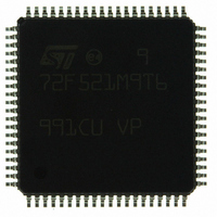
ST72F521M9T6 STMicroelectronics, ST72F521M9T6 Datasheet - Page 139

ST72F521M9T6
Manufacturer Part Number
ST72F521M9T6
Description
IC MCU 8BIT 60K FLASH 80-TQFP
Manufacturer
STMicroelectronics
Series
ST7r
Datasheet
1.ST72F521M9T6.pdf
(215 pages)
Specifications of ST72F521M9T6
Core Processor
ST7
Core Size
8-Bit
Speed
8MHz
Connectivity
CAN, LINSCI, SPI
Peripherals
LVD, POR, PWM, WDT
Number Of I /o
64
Program Memory Size
60KB (60K x 8)
Program Memory Type
FLASH
Ram Size
2K x 8
Voltage - Supply (vcc/vdd)
3.8 V ~ 5.5 V
Data Converters
A/D 16x10b
Oscillator Type
Internal
Operating Temperature
-40°C ~ 85°C
Package / Case
80-TQFP, 80-VQFP
Processor Series
ST72F5x
Core
ST7
Data Bus Width
8 bit
Data Ram Size
2048 B
Interface Type
CAN, I2C, SCI, SPI
Maximum Clock Frequency
8 MHz
Number Of Programmable I/os
64
Number Of Timers
5
Operating Supply Voltage
3.8 V to 5.5 V
Maximum Operating Temperature
+ 85 C
Mounting Style
SMD/SMT
Minimum Operating Temperature
- 40 C
On-chip Adc
10 bit
For Use With
497-6453 - BOARD EVAL BASED ON ST7LNBX497-5046 - KIT TOOL FOR ST7/UPSD/STR7 MCU
Lead Free Status / RoHS Status
Lead free / RoHS Compliant
Eeprom Size
-
Lead Free Status / Rohs Status
Details
Other names
497-8244
ST72F521M9T6
ST72F521M9T6
Available stocks
Company
Part Number
Manufacturer
Quantity
Price
Company:
Part Number:
ST72F521M9T6
Manufacturer:
ST
Quantity:
37 800
Company:
Part Number:
ST72F521M9T6
Manufacturer:
STMicroelectronics
Quantity:
10 000
Company:
Part Number:
ST72F521M9T6TR
Manufacturer:
STMicroelectronics
Quantity:
10 000
CONTROLLER AREA NETWORK (Cont’d)
BAUD RATE PRESCALER REGISTER (BRPR)
Read/Write in Standby mode
Reset Value: 00h
RJW[1:0] determine the maximum number of time
quanta by which a bit period may be shortened or
lengthened to achieve resynchronization.
t
BRP[5:0] determine the CAN system clock cycle
time or time quanta which is used to build up the in-
dividual bit timing.
t
Where t
The resulting baud rate can be computed by the for-
mula:
Note: Writing to this register is allowed only in
Standby mode to prevent any accidental CAN pro-
tocol violation through programming errors.
RJW
CAN
RJW1 RJW0 BRP5
BR
7
= t
= t
=
CPU
CAN
CPU
--------------------------------------------------------------------------------------------------- -
t
CPU
* (BRP + 1)
* (RJW + 1)
= time period of the CPU clock.
×
(
BRP
BRP4
+
1
BRP3
)
1
×
(
BS1
BRP2
+
BS2
BRP1
+
BRP0
3
)
0
BIT TIMING REGISTER (BTR)
Read/Write in Standby mode
Reset Value: 23h
BS2[2:0] determine the length of Bit Segment 2.
t
BS1[3:0] determine the length of Bit Segment 1.
t
Note: Writing to this register is allowed only in
Standby mode to prevent any accidental CAN pro-
tocol violation through programming errors.
PAGE SELECTION REGISTER (PSR)
Read/Write
Reset Value: 00h
PAGE[2:0] determine which buffer or filter page is
mapped at addresses 0010h to 001Fh.
BS2
BS1
7
0
7
0
PAGE2
= t
= t
0
0
0
0
1
1
1
1
CAN
CAN
BS22
0
* (BS2 + 1)
* (BS1 + 1)
BS21
0
PAGE1
0
0
1
1
0
0
1
1
BS20
0
ST72F521, ST72521B
BS13
0
PAGE0
0
1
0
1
0
1
0
1
PAGE
BS12
2
PAGE
BS11
Page Title
Diagnosis
Reserved
Reserved
Reserved
1
Buffer 1
Buffer 2
Buffer 3
Filters
139/215
PAGE
BS10
0
0
0


