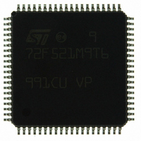
ST72F521M9T6 STMicroelectronics, ST72F521M9T6 Datasheet - Page 151

ST72F521M9T6
Manufacturer Part Number
ST72F521M9T6
Description
IC MCU 8BIT 60K FLASH 80-TQFP
Manufacturer
STMicroelectronics
Series
ST7r
Datasheet
1.ST72F521M9T6.pdf
(215 pages)
Specifications of ST72F521M9T6
Core Processor
ST7
Core Size
8-Bit
Speed
8MHz
Connectivity
CAN, LINSCI, SPI
Peripherals
LVD, POR, PWM, WDT
Number Of I /o
64
Program Memory Size
60KB (60K x 8)
Program Memory Type
FLASH
Ram Size
2K x 8
Voltage - Supply (vcc/vdd)
3.8 V ~ 5.5 V
Data Converters
A/D 16x10b
Oscillator Type
Internal
Operating Temperature
-40°C ~ 85°C
Package / Case
80-TQFP, 80-VQFP
Processor Series
ST72F5x
Core
ST7
Data Bus Width
8 bit
Data Ram Size
2048 B
Interface Type
CAN, I2C, SCI, SPI
Maximum Clock Frequency
8 MHz
Number Of Programmable I/os
64
Number Of Timers
5
Operating Supply Voltage
3.8 V to 5.5 V
Maximum Operating Temperature
+ 85 C
Mounting Style
SMD/SMT
Minimum Operating Temperature
- 40 C
On-chip Adc
10 bit
For Use With
497-6453 - BOARD EVAL BASED ON ST7LNBX497-5046 - KIT TOOL FOR ST7/UPSD/STR7 MCU
Lead Free Status / RoHS Status
Lead free / RoHS Compliant
Eeprom Size
-
Lead Free Status / Rohs Status
Details
Other names
497-8244
ST72F521M9T6
ST72F521M9T6
Available stocks
Company
Part Number
Manufacturer
Quantity
Price
Company:
Part Number:
ST72F521M9T6
Manufacturer:
ST
Quantity:
37 800
Company:
Part Number:
ST72F521M9T6
Manufacturer:
STMicroelectronics
Quantity:
10 000
Company:
Part Number:
ST72F521M9T6TR
Manufacturer:
STMicroelectronics
Quantity:
10 000
CONTROLLER AREA NETWORK (Cont’d)
The figures below show the abort behaviour in the
four possible cases.
Figure 76. Abort and successful transmission
In this case the abort request performed during the
transmission has no effect, as the first transmis-
sion is successful.
Figure 77. Abort and transmission delayed by
busy CAN bus
In this case the NRTX bit is set to abort the trans-
mission after the first attempt. As the first attempt
is successful the READY and BUSY bits are reset
by pCAN and the transmit buffer becomes empty.
An abort is no longer required.
Figure 78. Abort and error during transmission
In this case NRTX (abort request) is set before the
error, thus pCAN resets READY and BUSY after
TX RQST
ABORT RQST
CAN TX
CAN RX
LOCK
READY
BUSY
NRTX
TX RQST
ABORT RQST
CAN TX
CAN RX
LOCK
READY
BUSY
NRTX
TX RQST
ABORT RQST
CAN TX
CAN RX
LOCK
READY
BUSY
NRTX
Error
the error (the first attempt). The abort has been
successful and the transmit buffer is empty.
Figure 79. Abort and arbitration lost
In this case the NRTX bit is set but has no effect,
as the previous transmission attempt failed due to
an arbitration lost. The application waits for the
falling edge of BUSY bit and checks that READY is
still set. This is the case, this means pCAN has lost
the arbitration and LOCK bit can be safely reset.
Abort is immediate and pCAN resets the READY
and BUSY bits.
Timing Considerations
As no interrupt signals that an abort has been suc-
cessful, the application has to wait until the trans-
mit buffer is empty (transmission has been aborted
or transmitted successfully). This time can vary
depending on the case in which the abort is per-
formed (arbitration lost, error or successful trans-
mission). To show the impact of the software work-
around on this timing behaviour
ure 81
case when abort is done by LOCK only) with the
behaviour when NRTX, BUSY and LOCK bits are
used.
Figure 80. Abort by LOCK only - Reference
behaviour
TX RQST
CAN TX
CAN RX
LOCK
READY
BUSY
TX RQST
CAN TX
CAN RX
LOCK
READY
BUSY
ABORT RQST
NRTX
ABORT RQST
NRTX
compare the reference behaviour (worst
ST72F521, ST72521B
Figure 80
and
151/215
Fig-


