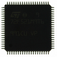
ST72F521M9T6 STMicroelectronics, ST72F521M9T6 Datasheet - Page 213

ST72F521M9T6
Manufacturer Part Number
ST72F521M9T6
Description
IC MCU 8BIT 60K FLASH 80-TQFP
Manufacturer
STMicroelectronics
Series
ST7r
Datasheet
1.ST72F521M9T6.pdf
(215 pages)
Specifications of ST72F521M9T6
Core Processor
ST7
Core Size
8-Bit
Speed
8MHz
Connectivity
CAN, LINSCI, SPI
Peripherals
LVD, POR, PWM, WDT
Number Of I /o
64
Program Memory Size
60KB (60K x 8)
Program Memory Type
FLASH
Ram Size
2K x 8
Voltage - Supply (vcc/vdd)
3.8 V ~ 5.5 V
Data Converters
A/D 16x10b
Oscillator Type
Internal
Operating Temperature
-40°C ~ 85°C
Package / Case
80-TQFP, 80-VQFP
Processor Series
ST72F5x
Core
ST7
Data Bus Width
8 bit
Data Ram Size
2048 B
Interface Type
CAN, I2C, SCI, SPI
Maximum Clock Frequency
8 MHz
Number Of Programmable I/os
64
Number Of Timers
5
Operating Supply Voltage
3.8 V to 5.5 V
Maximum Operating Temperature
+ 85 C
Mounting Style
SMD/SMT
Minimum Operating Temperature
- 40 C
On-chip Adc
10 bit
For Use With
497-6453 - BOARD EVAL BASED ON ST7LNBX497-5046 - KIT TOOL FOR ST7/UPSD/STR7 MCU
Lead Free Status / RoHS Status
Lead free / RoHS Compliant
Eeprom Size
-
Lead Free Status / Rohs Status
Details
Other names
497-8244
ST72F521M9T6
ST72F521M9T6
Available stocks
Company
Part Number
Manufacturer
Quantity
Price
Company:
Part Number:
ST72F521M9T6
Manufacturer:
ST
Quantity:
37 800
Company:
Part Number:
ST72F521M9T6
Manufacturer:
STMicroelectronics
Quantity:
10 000
Company:
Part Number:
ST72F521M9T6TR
Manufacturer:
STMicroelectronics
Quantity:
10 000
KNOWN LIMITATIONS (Cont’d)
15.2 ALL FLASH DEVICES
15.2.1 Internal RC Oscillator with LVD
The internal RC can only be used if LVD is ena-
bled.
15.2.2 I/O behaviour during ICC mode entry
sequence
Symptom
In 80-pin devices (Flash), both Port G and H are
forced to output push-pull during ICC mode entry
sequence. 80-pin ROM devices are not impacted
by this issue.
Details
To enable programming of all flash sectors, the
device must leave USER mode and be configured
in ICC mode. Once in ICC mode, the ICC protocol
enables an ST7 microcontroller to communicate
with an external controller (such as a PC). ICC
mode is entered by applying 39 pulses on the IC-
CDATA signal during reset. To enter ICC mode,
the device goes through other modes, some
modes are critical because the I/Os PG[7:0] and
PH[7:0] are forced to output push-pull.
Impact on the Application
The PG and PH I/O ports are forced to output
push-pull during three pulses on ICCDATA. In cer-
tain circumstances, this behaviour can lead to a
short-circuit between the I/O signals and V
or an output signal of another application compo-
nent.
In addition, switching these I/Os to output mode
can cause the application to leave reset state, dis-
turbing the ICC communication and preventing the
user from programming the flash.
15.2.3 Read-out protection with LVD
The LVD is not supported if Readout protection is
enabled.
ST72F521, ST72521B
DD
213/215
, V
SS


