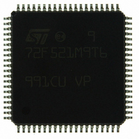
ST72F521M9T6 STMicroelectronics, ST72F521M9T6 Datasheet - Page 132

ST72F521M9T6
Manufacturer Part Number
ST72F521M9T6
Description
IC MCU 8BIT 60K FLASH 80-TQFP
Manufacturer
STMicroelectronics
Series
ST7r
Datasheet
1.ST72F521M9T6.pdf
(215 pages)
Specifications of ST72F521M9T6
Core Processor
ST7
Core Size
8-Bit
Speed
8MHz
Connectivity
CAN, LINSCI, SPI
Peripherals
LVD, POR, PWM, WDT
Number Of I /o
64
Program Memory Size
60KB (60K x 8)
Program Memory Type
FLASH
Ram Size
2K x 8
Voltage - Supply (vcc/vdd)
3.8 V ~ 5.5 V
Data Converters
A/D 16x10b
Oscillator Type
Internal
Operating Temperature
-40°C ~ 85°C
Package / Case
80-TQFP, 80-VQFP
Processor Series
ST72F5x
Core
ST7
Data Bus Width
8 bit
Data Ram Size
2048 B
Interface Type
CAN, I2C, SCI, SPI
Maximum Clock Frequency
8 MHz
Number Of Programmable I/os
64
Number Of Timers
5
Operating Supply Voltage
3.8 V to 5.5 V
Maximum Operating Temperature
+ 85 C
Mounting Style
SMD/SMT
Minimum Operating Temperature
- 40 C
On-chip Adc
10 bit
For Use With
497-6453 - BOARD EVAL BASED ON ST7LNBX497-5046 - KIT TOOL FOR ST7/UPSD/STR7 MCU
Lead Free Status / RoHS Status
Lead free / RoHS Compliant
Eeprom Size
-
Lead Free Status / Rohs Status
Details
Other names
497-8244
ST72F521M9T6
ST72F521M9T6
Available stocks
Company
Part Number
Manufacturer
Quantity
Price
Company:
Part Number:
ST72F521M9T6
Manufacturer:
ST
Quantity:
37 800
Company:
Part Number:
ST72F521M9T6
Manufacturer:
STMicroelectronics
Quantity:
10 000
Company:
Part Number:
ST72F521M9T6TR
Manufacturer:
STMicroelectronics
Quantity:
10 000
ST72F521, ST72521B
CONTROLLER AREA NETWORK (Cont’d)
10.8.3.3 Modes of Operation
The CAN Core unit assumes one of the seven
states described below:
– STANDBY. Standby mode is entered either on a
Figure 70. CAN Controller State Diagram
n
132/215
chip reset or on resetting the RUN bit in the Con-
trol/Status Register (CSR). Any on-going trans-
mission or reception operation is not interrupted
and completes normally before the Bit Time Log-
ic and the clock prescaler are turned off for mini-
mum power consumption. This state is signalled
by the RUN bit being read-back as 0.
Once in standby, the only event monitored is the
reception of a dominant bit which causes a wake-
up interrupt if the SCIE bit of the Interrupt Control
Register (ICR) is set.
The STANDBY mode is left by setting the RUN
Write to DATA7 |
TX Error & NRTX
TRANSMISSION
TX Error
RUN
RUN
TX OK
Arbitration lost
STANDBY
RESYNC
ARESET
ERROR
IDLE
FSYN & BOFF & 11 Recessive bits |
(FSYN | BOFF) & 128 * 11 Recessive bits
RX OK
Note: Standby mode is not entered on resetting
the RUN bit in the Control/Status register (CSR) if
the CANRX pin is shorted to GND.
– WAKE-UP. The CAN bus line is forced to domi-
RUN & WKPS
bit. If the WKPS bit is set in the CSR register,
then the controller passes through WAKE-UP
otherwise it enters RESYNC directly.
It is important to note that the wake-up mecha-
nism is software-driven and therefore carries a
significant time overhead. All messages received
after the wake-up bit and before the controller is
set to run and has completed synchronization
are ignored.
nant for one bit time signalling the wake-up con-
dition to all other bus members.
BOFF
BOFF
RUN & WKPS
RECEPTION
Start Of Frame
RX Error
WAKE-UP


