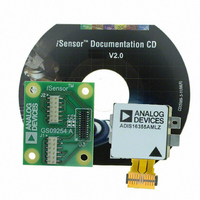
ADIS16355/PCBZ Analog Devices Inc, ADIS16355/PCBZ Datasheet - Page 3

ADIS16355/PCBZ
Manufacturer Part Number
ADIS16355/PCBZ
Description
BOARD EVAL FOR ADIS16355
Manufacturer
Analog Devices Inc
Series
iMEMS®, iSensor™r
Datasheets
1.ADIS16350PCBZ.pdf
(24 pages)
2.ADIS16350PCBZ.pdf
(2 pages)
3.ADIS16355PCBZ.pdf
(2 pages)
Specifications of ADIS16355/PCBZ
Sensor Type
Accelerometer, Gyroscope, 3 Axis
Sensing Range
±10g, ±75°/sec, ±150°/sec, ±300°/sec
Interface
SPI Serial
Sensitivity
2.522mg/LSB, 0.018°/sec/LSB
Voltage - Supply
4.75 V ~ 5.25 V
Embedded
No
Utilized Ic / Part
ADIS16355
For Use With
ADISUSBZ - KIT EVAL ADIS W/SOFTWARE USB
Lead Free Status / RoHS Status
Lead free / RoHS Compliant
Parameter
GYROSCOPE SENSITIVITY
GYROSCOPE BIAS
GYROSCOPE NOISE PERFORMANCE
GYROSCOPE FREQUENCY RESPONSE
GYROSCOPE SELF-TEST STATE
ACCELEROMETER SENSITIVITY
ACCELEROMETER BIAS
SPECIFICATIONS
T
Table 1.
A
Change for Positive Stimulus
Change for Negative Stimulus
Internal Self-Test Cycle Time
Dynamic Range
Initial Sensitivity
Temperature Coefficient
Nonlinearity
In-Run Bias Stability
Velocity Random Walk
Temperature Coefficient
Initial Sensitivity
Temperature Coefficient
Gyroscope Axis Nonorthogonality
Gyroscope Axis Misalignment
Nonlinearity
In Run Bias Stability
Angular Random Walk
Temperature Coefficient
Linear Acceleration Effect
Voltage Sensitivity
Output Noise
Rate Noise Density
3 dB Bandwidth
Sensor Resonant Frequency
Axis Nonorthogonality
Axis Misalignment
= −40°C to +85°C, V
CC
= 5.0 V, angular rate = 0°/s, dynamic range = 300°/s, ±1 g, unless otherwise noted.
Conditions
Each axis
25°C, dynamic range = ±300°/s
25°C, dynamic range = ±150°/s
25°C, dynamic range = ±75°/s
ADIS16350, see Figure 6
ADIS16355, see Figure 9
25°C, difference from 90° ideal
25°C, relative to base-plate and guide pins
Best fit straight line
25°C, 1 σ
25°C
ADIS16350, see Figure 7
ADIS16355, see Figure 10
Any axis, 1 σ (linear acceleration bias
compensation enabled)
V
25°C, ±300°/s range, 2-tap filter setting
25°C, ±150°/s range, 8-tap filter setting
25°C, ±75°/s range, 32-tap filter setting
25°C, f = 25 Hz, ±300°/s, no filtering
±300°/s range setting
±300°/s range setting
Each axis
25°C
ADIS16350, see Figure 8
ADIS16355, see Figure 11
25°C, difference from 90° ideal
25°C, relative to base-plate and guide pins
Best fit straight line
25°C, 1 σ
25°C
ADIS16350, see Figure 12
ADIS16355, see Figure 15
CC
= 4.75 V to 5.25 V
Rev. B | Page 3 of 24
Min
−432
0.0725
432
±8
2.471
ADIS16350/ADIS16355
Typ
0.07326
0.03663
0.01832
600
40
±0.05
±0.5
0.1
0.015
4.2
0.1
0.01
0.05
0.25
0.60
0.35
0.17
0.05
350
14
723
−723
25
±10
2.522
100
40
±0.25
±0.5
±0.2
0.7
2.0
4
0.5
Max
1105
−1105
2.572
0.0740
Unit
°/s/LSB
°/s/LSB
°/s/LSB
ppm/°C
ppm/°C
Degree
Degree
% of FS
°/s
°/√hr
°/s/°C
°/s/°C
°/s/g
°/s/V
°/s rms
°/s rms
°/s rms
°/s/√Hz rms
Hz
kHz
LSB
LSB
ms
g
mg/LSB
ppm/°C
ppm/°C
Degree
Degree
% of FS
mg
m/s/√hr
mg/°C
mg/°C


