ADIS16355/PCBZ Analog Devices Inc, ADIS16355/PCBZ Datasheet - Page 19
ADIS16355/PCBZ
Manufacturer Part Number
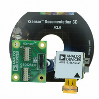
ADIS16355/PCBZ
Description
BOARD EVAL FOR ADIS16355
Manufacturer
Analog Devices Inc
Series
iMEMS®, iSensor™r
Datasheets
1.ADIS16350PCBZ.pdf
(24 pages)
2.ADIS16350PCBZ.pdf
(2 pages)
3.ADIS16355PCBZ.pdf
(2 pages)
Specifications of ADIS16355/PCBZ
Sensor Type
Accelerometer, Gyroscope, 3 Axis
Sensing Range
±10g, ±75°/sec, ±150°/sec, ±300°/sec
Interface
SPI Serial
Sensitivity
2.522mg/LSB, 0.018°/sec/LSB
Voltage - Supply
4.75 V ~ 5.25 V
Embedded
No
Utilized Ic / Part
ADIS16355
For Use With
ADISUSBZ - KIT EVAL ADIS W/SOFTWARE USB
Lead Free Status / RoHS Status
Lead free / RoHS Compliant


STATUS AND DIAGNOSTICS
Table 26 summarizes a number of status and diagnostic
operations, along with their corresponding control registers.
Table 26. Status and Diagnostic Functions
Register
MSC_CTRL
STATUS
ENDURANCE
ALM_MAG1
ALM_MAG2
ALM_SMPL1
ALM_SMPL2
ALM_CTRL
Data-Ready Input/Output Indicator
The data-ready function provides an indication of updated output
data. The MSC_CTRL register allows the user to configure either
of the general-purpose input/output pins (DIO1 or DIO2) as a
data-ready indicator signal.
Table 27. MSC_CTRL Register Definition
Address
0x35, 0x34
Table 28. MSC_CTRL Bit Descriptions
Bits
[15:11]
[10]
[9]
[8]
[7]
[6]
[5:3]
[2]
[1]
[0]
Description
Not used
Internal self-test enable (clears on completion)
Manual self-test, negative stimulus
Manual self-test, positive stimulus
Linear acceleration bias compensation for gyroscopes
Linear accelerometer origin alignment
Not used
Data-ready enable
Data-ready polarity
Data-ready line select
1 = enabled, 0 = disabled
1 = enabled, 0 = disabled
1 = enabled, 0 = disabled
1 = enabled, 0 = disabled
1 = enabled, 0 = disabled
1 = enabled, 0 = disabled
1 = active high, 0 = active low
1 = DIO2, 0 = DIO1
Function
Data-ready input/output indicator; self-test,
mechanical check for sensor element
Status: Check for predefined error conditions
Flash memory endurance
Alarms: Configure and check for user-specific
conditions
Default
0x0000
Format
N/A
Access
R/W
Rev. B | Page 19 of 24
Self-Test
The MSC_CTRL register also provides a self-test function that
verifies the mechanical integrity of the MEMS sensor. There are
two different self-test options: internal self-test and external
self-test.
The internal test provides a simple, two-step process for
checking the MEMS sensor.
1.
2.
If a failure is indicated, then Bits [10:15] of the STATUS register
indicate which of the six sensors it is associated with.
The entire cycle takes approximately 35 ms, and the output data
is not available during this time. The external self-test is a static
condition that can be enabled and disabled. In this test, both
positive and negative gyroscope MEMS sensor movements are
available. For the accelerometers, only positive MEMS sensor
movement is available.
After writing to the appropriate control bit, the output registers
reflect the changes after a delay that reflects the response time
associated with the sensor/signal conditioning circuit. For
example, the standard 350 Hz bandwidth reflects an exponential
response with a time constant of 0.45 ms. Note that the digital
filtering affects this delay as well. The appropriate bit definitions
for self-test are listed in Table 27 and Table 28.
Flash Memory Endurance
The ENDURANCE register maintains a running count of writes
to the flash memory. It provides up to 32,768 counts. Note that
if this count is exceeded, the register wraps around and goes
back to zero, before beginning to increment again.
Table 29. ENDURANCE Register Definition
Address
0x01, 0x00
Start the process by writing 1 to Bit 10 in the MSC_CTRL
register.
Wait long enough for the response to settle, then check the
result by reading Bit 5 of the STATUS register.
Default
N/A
ADIS16350/ADIS16355
Binary
Format
Access
Read only
Related parts for ADIS16355/PCBZ
Image
Part Number
Description
Manufacturer
Datasheet
Request
R

Part Number:
Description:
PC EVALUATION SYSTEM
Manufacturer:
Analog Devices Inc
Datasheet:

Part Number:
Description:
±1.7g Dual-Axis IMEMS Accelerometer Evaluation Board
Manufacturer:
Analog Devices Inc
Datasheet:
Part Number:
Description:
Inertial Sensor Evaluation System
Manufacturer:
Analog Devices Inc
Datasheet:
Part Number:
Description:
Manufacturer:
Analog Devices Inc
Datasheet:
Part Number:
Description:
Manufacturer:
Analog Devices Inc
Datasheet:
Part Number:
Description:
Manufacturer:
Analog Devices Inc
Datasheet:
Part Number:
Description:
Manufacturer:
Analog Devices Inc
Datasheet:
Part Number:
Description:
Manufacturer:
Analog Devices Inc
Datasheet:
Part Number:
Description:
Manufacturer:
Analog Devices Inc
Datasheet:
Part Number:
Description:
Manufacturer:
Analog Devices Inc
Datasheet:
Part Number:
Description:
Manufacturer:
Analog Devices Inc
Datasheet:
Part Number:
Description:
Manufacturer:
Analog Devices Inc
Datasheet:
Part Number:
Description:
Manufacturer:
Analog Devices Inc
Datasheet: