ADIS16355/PCBZ Analog Devices Inc, ADIS16355/PCBZ Datasheet - Page 15
ADIS16355/PCBZ
Manufacturer Part Number
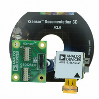
ADIS16355/PCBZ
Description
BOARD EVAL FOR ADIS16355
Manufacturer
Analog Devices Inc
Series
iMEMS®, iSensor™r
Datasheets
1.ADIS16350PCBZ.pdf
(24 pages)
2.ADIS16350PCBZ.pdf
(2 pages)
3.ADIS16355PCBZ.pdf
(2 pages)
Specifications of ADIS16355/PCBZ
Sensor Type
Accelerometer, Gyroscope, 3 Axis
Sensing Range
±10g, ±75°/sec, ±150°/sec, ±300°/sec
Interface
SPI Serial
Sensitivity
2.522mg/LSB, 0.018°/sec/LSB
Voltage - Supply
4.75 V ~ 5.25 V
Embedded
No
Utilized Ic / Part
ADIS16355
For Use With
ADISUSBZ - KIT EVAL ADIS W/SOFTWARE USB
Lead Free Status / RoHS Status
Lead free / RoHS Compliant


PROGRAMMING AND CONTROL
CONTROL REGISTER OVERVIEW
There are many programmable features that are controlled by
writing commands to the appropriate control registers using the
SPI. The following sections describe these controls and specify
each function, along with the corresponding register configuration.
The features available for configuration in this register space are:
Table 9. Control Register Mapping
Register Name
ENDURANCE
XGYRO_OFF
YGYRO_OFF
ZGYRO_OFF
XACCL_OFF
YACCL_OFF
ZACCL_OFF
ALM_MAG1
ALM_MAG2
ALM_SMPL1
ALM_SMPL2
ALM_CTRL
AUX_DAC
GPIO_CTRL
MSC_CTRL
SMPL_PRD
SENS/AVG
SLP_CNT
STATUS
COMMAND
1
•
•
•
•
The contents of the lower byte are nonvolatile; the contents of the upper byte are volatile.
Calibration
Global commands
Operational control
Operational status and diagnostics
•
•
•
•
•
•
•
•
•
Sample rate
Power management
Digital filtering
Dynamic range
DAC output
Digital input/output
Self-test
Status conditions
Alarms
Type
R
R/W
R/W
R/W
R/W
R/W
R/W
R/W
R/W
R/W
R/W
W
R
R/W
R/W
R/W
R/W
R/W
R/W
R/W
R
Volatility
Nonvolatile
Volatile
Nonvolatile
Nonvolatile
Nonvolatile
Nonvolatile
Nonvolatile
Nonvolatile
Nonvolatile
Nonvolatile
Nonvolatile
Volatile
Volatile
Nonvolatile
Nonvolatile
Nonvolatile
Volatile
Volatile
N/A
Nonvolatile
Nonvolatile
1
Addresses
0x00, 0x01
0x18, 0x19
0x1C, 0x1D
0x1E, 0x1F
0x20, 0x21
0x22, 0x23
0x24, 0x25
0x26, 0x27
0x28, 0x29
0x2A, 0x2B
0x2C, 0x2D
0x2E, 0x2F
0x30, 0x31
0x32, 0x33
0x34, 0x35
0x36, 0x37
0x38, 0x39
0x3A, 0x3B
0x3C, 0x3D
0x3E, 0x3F
0x02 to 0x17
0x1A, 0x1B
Bytes
2
2
2
2
2
2
2
2
2
2
2
2
2
2
2
2
2
2
2
2
2
22
Rev. B | Page 15 of 24
Function
Flash memory write count
Output data
Reserved
X-axis gyroscope bias offset factor
Y-axis gyroscope bias offset factor
Z-axis gyroscope bias offset factor
X-axis acceleration bias offset factor
Y-axis acceleration bias offset factor
Z-axis acceleration bias offset factor
Alarm 1 amplitude threshold
Alarm 2 amplitude threshold
Alarm 1 sample size
Alarm 2 sample size
Alarm control
Auxiliary DAC data
Auxiliary digital input/output control
Miscellaneous control
Internal sample period (rate) control
Dynamic range/digital filter control
Sleep mode control
System status
System command
CONTROL REGISTER STRUCTURE
The ADIS16350/ADIS16355 use a temporary, RAM-based
memory structure to facilitate the control registers listed
in Table 9. The operational configuration is stored in a flash
memory structure that automatically loads into the control
registers during the start-up sequence. Each nonvolatile register
has a corresponding flash memory location for storing the latest
configuration contents. The contents of each nonvolatile regis-
ter must be stored to flash manually.
Note that the contents of these registers are nonvolatile after they
are stored to flash. The flash update command, available in the
COMMAND register, provides this function. The ENDURANCE
register provides a counter that allows for reliability manage-
ment against the flash memory write cycle specification.
ADIS16350/ADIS16355
Reference Tables
Table 29
Table 6
Table 10, Table 11
Table 10, Table 11
Table 10, Table 11
Table 12, Table 13
Table 12, Table 13
Table 12, Table 13
Table 32, Table 33
Table 32, Table 33
Table 34, Table 35
Table 34, Table 35
Table 36, Table 37
Table 22, Table 23
Table 24, Table 25
Table 27, Table 28
Table 16, Table 17
Table 20, Table 21
Table 18, Table 19
Table 30, Table 31
Table 14, Table 15
Related parts for ADIS16355/PCBZ
Image
Part Number
Description
Manufacturer
Datasheet
Request
R

Part Number:
Description:
PC EVALUATION SYSTEM
Manufacturer:
Analog Devices Inc
Datasheet:

Part Number:
Description:
±1.7g Dual-Axis IMEMS Accelerometer Evaluation Board
Manufacturer:
Analog Devices Inc
Datasheet:
Part Number:
Description:
Inertial Sensor Evaluation System
Manufacturer:
Analog Devices Inc
Datasheet:
Part Number:
Description:
Manufacturer:
Analog Devices Inc
Datasheet:
Part Number:
Description:
Manufacturer:
Analog Devices Inc
Datasheet:
Part Number:
Description:
Manufacturer:
Analog Devices Inc
Datasheet:
Part Number:
Description:
Manufacturer:
Analog Devices Inc
Datasheet:
Part Number:
Description:
Manufacturer:
Analog Devices Inc
Datasheet:
Part Number:
Description:
Manufacturer:
Analog Devices Inc
Datasheet:
Part Number:
Description:
Manufacturer:
Analog Devices Inc
Datasheet:
Part Number:
Description:
Manufacturer:
Analog Devices Inc
Datasheet:
Part Number:
Description:
Manufacturer:
Analog Devices Inc
Datasheet:
Part Number:
Description:
Manufacturer:
Analog Devices Inc
Datasheet: