ADIS16355/PCBZ Analog Devices Inc, ADIS16355/PCBZ Datasheet - Page 2
ADIS16355/PCBZ
Manufacturer Part Number
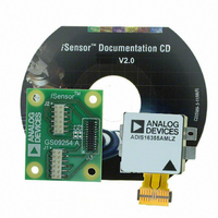
ADIS16355/PCBZ
Description
BOARD EVAL FOR ADIS16355
Manufacturer
Analog Devices Inc
Series
iMEMS®, iSensor™r
Datasheets
1.ADIS16350PCBZ.pdf
(24 pages)
2.ADIS16350PCBZ.pdf
(2 pages)
3.ADIS16355PCBZ.pdf
(2 pages)
Specifications of ADIS16355/PCBZ
Sensor Type
Accelerometer, Gyroscope, 3 Axis
Sensing Range
±10g, ±75°/sec, ±150°/sec, ±300°/sec
Interface
SPI Serial
Sensitivity
2.522mg/LSB, 0.018°/sec/LSB
Voltage - Supply
4.75 V ~ 5.25 V
Embedded
No
Utilized Ic / Part
ADIS16355
For Use With
ADISUSBZ - KIT EVAL ADIS W/SOFTWARE USB
Lead Free Status / RoHS Status
Lead free / RoHS Compliant


ADIS16350/ADIS16355
TABLE OF CONTENTS
Features .............................................................................................. 1
Applications ....................................................................................... 1
Functional Block Diagram .............................................................. 1
General Description ......................................................................... 1
Revision History ............................................................................... 2
Specifications ..................................................................................... 3
Absolute Maximum Ratings ............................................................ 7
Pin Configuration and Function Descriptions ............................. 8
Typical Performance Characteristics ............................................. 9
Theory of Operation ...................................................................... 12
REVISION HISTORY
9/09—Rev. A to Rev. B
Changes to Figure 4 and Figure 5 ................................................... 7
Changes to Ordering Guide .......................................................... 24
2/08—Rev. 0 to Rev. A
Added ADIS16355 .............................................................. Universal
Changes to Features .......................................................................... 1
Changes to General Description .................................................... 1
Changes to Temperature Coefficient Throughout Table 1 and
Gyroscope Noise Performance Output Noise ............................... 3
Changes to Output Range ................................................................ 4
Added Endnote 1 .............................................................................. 5
Changes to Table 3 ............................................................................ 7
Inserted Figure 4 ............................................................................... 8
Deleted Figure 10 .............................................................................. 8
Inserted Figure 9, Figure 10, and Figure 11 .................................. 9
Deleted Figure 12 .............................................................................. 9
Changes to Figure 13 and Figure 14 ............................................. 10
Timing Specifications .................................................................. 6
Timing Diagrams .......................................................................... 6
ESD Caution .................................................................................. 7
Overview ...................................................................................... 12
Gyroscope Sensor ....................................................................... 12
Accelerometer Sensor ................................................................ 12
Factory Calibration .................................................................... 12
Rev. B | Page 2 of 24
Basic Operation .............................................................................. 13
Programming and Control ............................................................ 15
Applications Information .............................................................. 22
Outline Dimensions ....................................................................... 24
Inserted Figure 15 ........................................................................... 10
Deleted Figure 17, Figure 18, Figure 20, and Figure 21............. 10
Changes to Factory Calibration Section ...................................... 12
Changes to Writing to Registers Section ..................................... 13
Replaced Data Output Register Access Section ......................... 14
Deleted Figure 28 ............................................................................ 15
Changes to Table 9 .......................................................................... 15
Changes to Global Commands Section ....................................... 16
Changes to Internal Sample Rate Section ................................... 17
Changes to Auxiliary DAC Section .............................................. 18
Changes to General-Purpose Input/Output Section ................. 18
Changes to Table 37 ....................................................................... 21
Changes to Installation Guidelines Section ................................ 22
Updated Outline Dimensions ....................................................... 24
Changes to Ordering Guide .......................................................... 24
8/07—Revision 0: Initial Version
Control Register Structure ........................................................ 12
Auxiliary ADC Function ........................................................... 12
Serial Peripheral Interface (SPI) ............................................... 13
Data Output Register Access .................................................... 14
Control Register Overview ....................................................... 15
Control Register Structure ........................................................ 15
Calibration ................................................................................... 16
Global Commands ..................................................................... 16
Operational Control ................................................................... 17
Status and Diagnostics ............................................................... 19
Installation Guidelines ............................................................... 22
Ordering Guide .......................................................................... 24
Related parts for ADIS16355/PCBZ
Image
Part Number
Description
Manufacturer
Datasheet
Request
R

Part Number:
Description:
PC EVALUATION SYSTEM
Manufacturer:
Analog Devices Inc
Datasheet:

Part Number:
Description:
±1.7g Dual-Axis IMEMS Accelerometer Evaluation Board
Manufacturer:
Analog Devices Inc
Datasheet:
Part Number:
Description:
Inertial Sensor Evaluation System
Manufacturer:
Analog Devices Inc
Datasheet:
Part Number:
Description:
Manufacturer:
Analog Devices Inc
Datasheet:
Part Number:
Description:
Manufacturer:
Analog Devices Inc
Datasheet:
Part Number:
Description:
Manufacturer:
Analog Devices Inc
Datasheet:
Part Number:
Description:
Manufacturer:
Analog Devices Inc
Datasheet:
Part Number:
Description:
Manufacturer:
Analog Devices Inc
Datasheet:
Part Number:
Description:
Manufacturer:
Analog Devices Inc
Datasheet:
Part Number:
Description:
Manufacturer:
Analog Devices Inc
Datasheet:
Part Number:
Description:
Manufacturer:
Analog Devices Inc
Datasheet:
Part Number:
Description:
Manufacturer:
Analog Devices Inc
Datasheet:
Part Number:
Description:
Manufacturer:
Analog Devices Inc
Datasheet: