ADIS16355/PCBZ Analog Devices Inc, ADIS16355/PCBZ Datasheet - Page 14
ADIS16355/PCBZ
Manufacturer Part Number
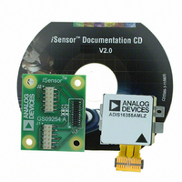
ADIS16355/PCBZ
Description
BOARD EVAL FOR ADIS16355
Manufacturer
Analog Devices Inc
Series
iMEMS®, iSensor™r
Datasheets
1.ADIS16350PCBZ.pdf
(24 pages)
2.ADIS16350PCBZ.pdf
(2 pages)
3.ADIS16355PCBZ.pdf
(2 pages)
Specifications of ADIS16355/PCBZ
Sensor Type
Accelerometer, Gyroscope, 3 Axis
Sensing Range
±10g, ±75°/sec, ±150°/sec, ±300°/sec
Interface
SPI Serial
Sensitivity
2.522mg/LSB, 0.018°/sec/LSB
Voltage - Supply
4.75 V ~ 5.25 V
Embedded
No
Utilized Ic / Part
ADIS16355
For Use With
ADISUSBZ - KIT EVAL ADIS W/SOFTWARE USB
Lead Free Status / RoHS Status
Lead free / RoHS Compliant


ADIS16350/ADIS16355
DATA OUTPUT REGISTER ACCESS
Table 6 provides the data configuration for each output data
register in the ADIS16350/ADIS16355. Starting with the MSB
of the upper byte, each output data register has the following bit
sequence: new data (ND) flag, error/alarm (EA) flag, followed
by 14 data bits. The data bits are LSB-justified and, in the case of
the 12-bit data formats, the remaining two bits (Bit 12 and Bit
Table 6. Output Data Register Information
Name
SUPPLY_OUT
XGYRO_OUT
YGYRO_OUT
ZGYRO_OUT
XACCL_OUT
YACCL_OUT
ZACCL_OUT
XTEMP_OUT
YTEMP_OUT
ZTEMP_OUT
AUX_ADC
1
2
3
Table 7. Output Coding Example, XGYRO_OUT, YGYRO_OUT, and ZGYRO_OUT
±300°/s Range
80°/s
40°/s
0.07326°/s
0°/s
−0.07326°/s
−40°/s
−80°/s
1
2
Table 8. Output Coding Example, XACCL_OUT, YACCL_OUT, and ZACCL_OUT
Acceleration (g)
2.522
1
0.002522
0
−0.002522
−1
−2.522
1
2
5 V = 2730 LSBs (nominal)
Assumes that the scaling is set to 300°/s.
Typical condition, 25°C = 0 LSB.
The two most significant bits are not included.
Zero offset null performance is assumed.
The two most significant bits are not included.
Zero offset null performance is assumed.
Function
Power supply measurement
X-axis gyroscope output measurement
Y-axis gyroscope output measurement
Z-axis gyroscope output measurement
X-axis acceleration output measurement
Y-axis acceleration output measurement
Z-axis acceleration output measurement
X-axis gyroscope sensor temperature measurement
Y-axis gyroscope sensor temperature measurement
Z-axis gyroscope sensor temperature measurement
Auxiliary analog input data
Rate of Rotation
±150°/s Range
40°/s
20°/s
0.03663°/s
0°/s
−0.03663°/s
−20°/s
−40°/s
Binary Output
00 0011 1110 1000
00 0001 1000 1101
00 0000 0000 0001
00 0000 0000 0000
11 1111 1111 1111
11 1110 0111 0011
11 1100 0001 1000
±75°/s Range
20°/s
10°/s
0.018315°/s
0°/s
−0.018315°/s
−10°/s
−20°/s
Rev. B | Page 14 of 24
Binary Output
00 0100 0100 0100
00 0010 0010 0010
00 0000 0000 0001
00 0000 0000 0000
11 1111 1111 1111
11 1101 1101 1110
11 1011 1011 1100
13) are not used. The ND flag indicates that unread data resides
in the output data registers. This flag clears and returns to 0
during an output register read sequence. It returns to 1 after the
next internal sample update cycle completes. The EA flag indi-
cates an error condition. The STATUS register contains all of
the error flags and provides the ability to investigate root cause.
Addresses
0x03, 0x02
0x05, 0x04
0x07, 0x06
0x09, 0x08
0x0B, 0x0A
0x0D, 0x0C
0x0F, 0x0E
0x11, 0x10
0x13, 0x12
0x15, 0x14
0x17, 0x16
Hexadecimal Output
0x03E8
0x018D
0x0001
0x0000
0x3FFF
0x3E73
0x3C18
1, 2
Data
Length
14 bits
14 bits
14 bits
12 bits
12 bits
14 bits
14 bits
14 bits
12 bits
12 bits
12 bits
1, 2
Hexadecimal Output
0x0444
0x0222
0x0001
0x0000
0x3FFF
0x3DDE
0x3BBC
Data Format
Binary
Twos complement
Twos complement
Twos complement
Twos complement
Twos complement
Twos complement
Twos complement
Twos complement
Twos complement
Binary
Decimal
1000
397
1
0
−1
−397
−1000
Scale Factor
(per LSB)
1.8315 mV
0.07326°/s
0.07326°/s
0.07326°/s
2.522 mg
2.522 mg
2.522 mg
0.1453°C
0.1453°C
0.1453°C
0.6105 mV
Decimal
1092
546
1
0
−1
−546
−1092
3
3
3
2
2
1
2
Related parts for ADIS16355/PCBZ
Image
Part Number
Description
Manufacturer
Datasheet
Request
R

Part Number:
Description:
PC EVALUATION SYSTEM
Manufacturer:
Analog Devices Inc
Datasheet:

Part Number:
Description:
±1.7g Dual-Axis IMEMS Accelerometer Evaluation Board
Manufacturer:
Analog Devices Inc
Datasheet:
Part Number:
Description:
Inertial Sensor Evaluation System
Manufacturer:
Analog Devices Inc
Datasheet:
Part Number:
Description:
Manufacturer:
Analog Devices Inc
Datasheet:
Part Number:
Description:
Manufacturer:
Analog Devices Inc
Datasheet:
Part Number:
Description:
Manufacturer:
Analog Devices Inc
Datasheet:
Part Number:
Description:
Manufacturer:
Analog Devices Inc
Datasheet:
Part Number:
Description:
Manufacturer:
Analog Devices Inc
Datasheet:
Part Number:
Description:
Manufacturer:
Analog Devices Inc
Datasheet:
Part Number:
Description:
Manufacturer:
Analog Devices Inc
Datasheet:
Part Number:
Description:
Manufacturer:
Analog Devices Inc
Datasheet:
Part Number:
Description:
Manufacturer:
Analog Devices Inc
Datasheet:
Part Number:
Description:
Manufacturer:
Analog Devices Inc
Datasheet: