ADIS16355/PCBZ Analog Devices Inc, ADIS16355/PCBZ Datasheet - Page 12
ADIS16355/PCBZ
Manufacturer Part Number
ADIS16355/PCBZ
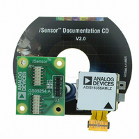
Description
BOARD EVAL FOR ADIS16355
Manufacturer
Analog Devices Inc
Series
iMEMS®, iSensor™r
Datasheets
1.ADIS16350PCBZ.pdf
(24 pages)
2.ADIS16350PCBZ.pdf
(2 pages)
3.ADIS16355PCBZ.pdf
(2 pages)
Specifications of ADIS16355/PCBZ
Sensor Type
Accelerometer, Gyroscope, 3 Axis
Sensing Range
±10g, ±75°/sec, ±150°/sec, ±300°/sec
Interface
SPI Serial
Sensitivity
2.522mg/LSB, 0.018°/sec/LSB
Voltage - Supply
4.75 V ~ 5.25 V
Embedded
No
Utilized Ic / Part
ADIS16355
For Use With
ADISUSBZ - KIT EVAL ADIS W/SOFTWARE USB
Lead Free Status / RoHS Status
Lead free / RoHS Compliant


ADIS16350/ADIS16355
THEORY OF OPERATION
OVERVIEW
The ADIS16350/ADIS16355 integrate three orthogonal axes of
gyroscope sensors with three orthogonal axes of accelerometer
sensors, creating the basic six degrees of freedom (6DOF) in a
single package. The accelerometers are oriented along the axis
of rotation for each gyroscope. These six sensing elements are
held together by a mechanical structure that provides tight force
and motion coupling. Each sensor output signal is sampled
using an ADC, and then the digital data is fed into a proprietary
digital processing circuit. The digital processing circuit applies
the correction tables to each sensor output, manages the input/
output function using a simple register structure and serial
interface, and provides many other features that simplify system-
level designs.
GYROSCOPE SENSOR
The core MEMs angular rate sensor (gyroscope) operates on the
principle of a resonator gyroscope. Two polysilicon sensing struc-
tures each contain a dither frame, which is electrostatically driven
to resonance. This provides the velocity element required to
produce a Coriolis force during rotation. At two of the outer
extremes of each frame, orthogonal to the dither motion, are
movable fingers that are placed between fixed fingers to form
a capacitive pickoff structure that senses Coriolis motion. The
resulting signal is fed to a series of gain and demodulation stages
that produce the electrical rate signal output.
ACCELEROMETER SENSOR
The core acceleration sensor is a surface micromachined
polysilicon structure built on top of the silicon wafer. Polysilicon
springs suspend the structure over the surface of the wafer and
provide a resistance against acceleration forces. Deflection of the
structure is measured using a differential capacitor that consists
of independent fixed plates and central plates attached to the
moving mass. Acceleration deflects the beam and unbalances
the differential capacitor, resulting in a differential output that is
fed to a series of gain and demodulation stages that produce the
electrical rate signal output.
FACTORY CALIBRATION
The ADIS16350 provides a factory calibration that simplifies
the process of integrating it into system-level designs. This
calibration provides correction for initial sensor bias and
sensitivity, power supply variation, axial alignment, and linear
acceleration (gyroscopes). An extensive, three-dimensional
characterization provides the basis for generating correction
tables for each individual sensor. The ADIS16355 provides the
same calibration, over temperature.
Rev. B | Page 12 of 24
CONTROL REGISTER STRUCTURE
The ADIS16350/ADIS16355 provide configuration control to
many critical operating parameters by using a dual-memory
register structure. The volatile SRAM register locations control
operation of the part while the nonvolatile flash memory
locations preserve the configuration settings. Updating register
contents affects only its SRAM location. Preserving the updates
in its corresponding flash memory location requires initiation
of the flash update command. This helps reduce the number of
write cycles to the flash memory and consequently increases the
endurance of the flash memory. During startup and reset-recovery
sequences, the flash memory contents are automatically loaded
into the SRAM register locations.
AUXILIARY ADC FUNCTION
The auxiliary ADC is a standard 12-bit ADC that digitizes other
system-level analog signals. The output of the ADC can be moni-
tored through the AUX_ADC register, as defined in Table 6.
The ADC is a 12-bit successive approximation converter. The
output data is presented in straight binary format with the full-
scale range extending from 0 V to 2.5 V.
Figure 24 shows the equivalent circuit of the analog input
structure of the ADC. The input capacitor (C1) is typically 4 pF
and can be attributed to parasitic package capacitance. The two
diodes provide ESD protection for the analog input. Care must
be taken to ensure that the analog input signals are never outside
the range of −0.3 V to +3.5 V. Signals outside this range causes
the diodes to become forward-biased and to start conducting.
The diodes can handle 10 mA without causing irreversible
damage. The resistor is a lumped component that represents
the on resistance of the switches. The value of this resistance is
typically 100 Ω. Capacitor C2 represents the ADC sampling
capacitor and is typically 16 pF.
For ac applications, it is recommended that high frequency
components from the analog input signal be removed by using
a low-pass filter on the analog input pin.
In applications where harmonic distortion and signal-to-noise
ratios are critical, the analog input must be driven from a low
impedance source. Large source impedances significantly affect
the ac performance of the ADC. This can necessitate the use of
an input buffer amplifier. When no input amplifier is used to drive
the analog input, the source impedance should be limited to
values lower than 1 kΩ.
Figure 24. Equivalent Analog Input Circuit
Conversion Phase: Switch Open
C1
Track Phase: Switch Closed
VDD
D
D
R1
C2
Related parts for ADIS16355/PCBZ
Image
Part Number
Description
Manufacturer
Datasheet
Request
R

Part Number:
Description:
PC EVALUATION SYSTEM
Manufacturer:
Analog Devices Inc
Datasheet:

Part Number:
Description:
±1.7g Dual-Axis IMEMS Accelerometer Evaluation Board
Manufacturer:
Analog Devices Inc
Datasheet:
Part Number:
Description:
Inertial Sensor Evaluation System
Manufacturer:
Analog Devices Inc
Datasheet:
Part Number:
Description:
Manufacturer:
Analog Devices Inc
Datasheet:
Part Number:
Description:
Manufacturer:
Analog Devices Inc
Datasheet:
Part Number:
Description:
Manufacturer:
Analog Devices Inc
Datasheet:
Part Number:
Description:
Manufacturer:
Analog Devices Inc
Datasheet:
Part Number:
Description:
Manufacturer:
Analog Devices Inc
Datasheet:
Part Number:
Description:
Manufacturer:
Analog Devices Inc
Datasheet:
Part Number:
Description:
Manufacturer:
Analog Devices Inc
Datasheet:
Part Number:
Description:
Manufacturer:
Analog Devices Inc
Datasheet:
Part Number:
Description:
Manufacturer:
Analog Devices Inc
Datasheet:
Part Number:
Description:
Manufacturer:
Analog Devices Inc
Datasheet: