ADIS16355/PCBZ Analog Devices Inc, ADIS16355/PCBZ Datasheet - Page 22
ADIS16355/PCBZ
Manufacturer Part Number
ADIS16355/PCBZ
Description
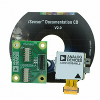
BOARD EVAL FOR ADIS16355
Manufacturer
Analog Devices Inc
Series
iMEMS®, iSensor™r
Datasheets
1.ADIS16350PCBZ.pdf
(24 pages)
2.ADIS16350PCBZ.pdf
(2 pages)
3.ADIS16355PCBZ.pdf
(2 pages)
Specifications of ADIS16355/PCBZ
Sensor Type
Accelerometer, Gyroscope, 3 Axis
Sensing Range
±10g, ±75°/sec, ±150°/sec, ±300°/sec
Interface
SPI Serial
Sensitivity
2.522mg/LSB, 0.018°/sec/LSB
Voltage - Supply
4.75 V ~ 5.25 V
Embedded
No
Utilized Ic / Part
ADIS16355
For Use With
ADISUSBZ - KIT EVAL ADIS W/SOFTWARE USB
Lead Free Status / RoHS Status
Lead free / RoHS Compliant


ADIS16350/ADIS16355
APPLICATIONS INFORMATION
INSTALLATION GUIDELINES
Installation requires two steps: mechanical attachment of the body,
followed by the electrical connection. This device is designed
for postsolder reflow installation. It is not designed to survive
the temperatures associated with normal solder reflow processes.
Mechanical Attachment
The open mounting tabs on each side of the body provide
enough room for 2 mm (or 2-56) machine screws. Note that
316 stainless steel and aluminum screws are available for use in
this attachment.
When planning the installation process, the primary trade-off
to consider is the attachment strength advantage of stainless
steel against the nonmagnetic properties of aluminum for systems
that are sensitive to magnetic field disturbances.
Figure 28 provides a graphical display of the mechanical
attachment, and Figure 29 provides a recommendation for the
physical layout of all the holes required for attaching these
devices.
FOR 2mm (2-56) SCREW,
DRILL AND TAP HOLE
2 EACH
Figure 28. Mechanical Attachment
Rev. B | Page 22 of 24
Electrical Connections
The electrical interface is a single connector that is attached to a
flexible circuit extension.
One option for mating connectors can be found in the Samtec
CLM family. In this case, the part number starts with CLM-112-02.
The flexible circuit has stress relief points to absorb environmental
stresses, such as temperature cycling and vibration. Figure 29
provides the alignment hole locations for designs that employ the
suggested connector mate. The dimensions offered in Figure 29
assume that the device and the mating connector are on the
same surface. The electrical connection is held by friction only.
Proper Removal
The flexible circuit interface can tear under excessive force
conditions. An example of excessive force is attempting to
break the electrical connection by pulling on the body of the
device, placing all of the stress on the flexible circuit.
The electrical connector must be broken by an appropriate tool,
which is designed to apply even pressure to each side of the
rigid part of the flex cable. The recommended extraction
sequence is to break the mate between the electrical interface,
and then to remove the mechanical attachment hardware.
1.588mm HOLE AND SLOT
FOR ALIGNMENT PINS, 2 EACH
Related parts for ADIS16355/PCBZ
Image
Part Number
Description
Manufacturer
Datasheet
Request
R

Part Number:
Description:
PC EVALUATION SYSTEM
Manufacturer:
Analog Devices Inc
Datasheet:

Part Number:
Description:
±1.7g Dual-Axis IMEMS Accelerometer Evaluation Board
Manufacturer:
Analog Devices Inc
Datasheet:
Part Number:
Description:
Inertial Sensor Evaluation System
Manufacturer:
Analog Devices Inc
Datasheet:
Part Number:
Description:
Manufacturer:
Analog Devices Inc
Datasheet:
Part Number:
Description:
Manufacturer:
Analog Devices Inc
Datasheet:
Part Number:
Description:
Manufacturer:
Analog Devices Inc
Datasheet:
Part Number:
Description:
Manufacturer:
Analog Devices Inc
Datasheet:
Part Number:
Description:
Manufacturer:
Analog Devices Inc
Datasheet:
Part Number:
Description:
Manufacturer:
Analog Devices Inc
Datasheet:
Part Number:
Description:
Manufacturer:
Analog Devices Inc
Datasheet:
Part Number:
Description:
Manufacturer:
Analog Devices Inc
Datasheet:
Part Number:
Description:
Manufacturer:
Analog Devices Inc
Datasheet:
Part Number:
Description:
Manufacturer:
Analog Devices Inc
Datasheet: