ADIS16355/PCBZ Analog Devices Inc, ADIS16355/PCBZ Datasheet - Page 16
ADIS16355/PCBZ
Manufacturer Part Number
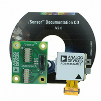
ADIS16355/PCBZ
Description
BOARD EVAL FOR ADIS16355
Manufacturer
Analog Devices Inc
Series
iMEMS®, iSensor™r
Datasheets
1.ADIS16350PCBZ.pdf
(24 pages)
2.ADIS16350PCBZ.pdf
(2 pages)
3.ADIS16355PCBZ.pdf
(2 pages)
Specifications of ADIS16355/PCBZ
Sensor Type
Accelerometer, Gyroscope, 3 Axis
Sensing Range
±10g, ±75°/sec, ±150°/sec, ±300°/sec
Interface
SPI Serial
Sensitivity
2.522mg/LSB, 0.018°/sec/LSB
Voltage - Supply
4.75 V ~ 5.25 V
Embedded
No
Utilized Ic / Part
ADIS16355
For Use With
ADISUSBZ - KIT EVAL ADIS W/SOFTWARE USB
Lead Free Status / RoHS Status
Lead free / RoHS Compliant


ADIS16350/ADIS16355
CALIBRATION
For applications that require point-of-use calibration, the bias
correction registers provide bias level control for all six sensors.
Table 10, Table 11, Table 12, and Table 13 provide the details
required for using these registers to calibrate the output bias for
each sensor.
Table 10. Gyroscope Bias Correction Registers
Register
XGYRO_OFF
YGYRO_OFF
ZGYRO_OFF
Table 11. Gyroscope Bias Correction Register Bits
Bits
[15:13]
[12:0]
Table 12. Accelerometer Bias Correction Registers
Register
XACCL_OFF
YACCL_OFF
ZACCL_OFF
Table 13. Accelerometer Bias Correction Register Bits
Bits
[15:12]
[11:0]
Manual Bias Calibration
Because each offset bias register has read/write access, the bias
of each sensor is adjustable. For example, if an output offset of
0.18°/s is observed in the Z-axis gyroscope, the ZGYRO_OFF
register provides the calibration factor necessary to improve the
accuracy. Using its sensitivity of 0.018315°/s, an adjustment of
−10 LSBs is required. The twos complement, hexadecimal code
of −10 LSBs is 0x1FF6.
To implement this calibration factor, use the following pseudocode:
This step reduces the 0.18°/s error term to 0.00315°/s.
Automatic Bias Null Calibration
A single-command, automatic bias calibration measures all
three gyroscope output registers, then loads the three bias
correction registers with values that return their outputs to zero
(null). A single register write command starts this process (see
Table 15).
Write 0xF6 to Address 0x1E, then write 0x1F to
Address 0x1F
Write 0x01 to Address 0x3E
Description
Not used
Data bits, typical adjustment range = ±75°
Description
Not used
Data bits, typical adjustment range = ±5.16 g
Addresses
0x1A, 0x1B
0x1C, 0x1D
0x1E, 0x1F
Addresses
0x21, 0x20
0x23, 0x22
0x25, 0x24
Scale = 2.522 mg per LSB
Twos complement, read/write
Common Parameters
Default value = 0x0000
Scale = 0.018315°/s per LSB
Twos complement, read/write
Common Parameters
Default value = 0x0000
Rev. B | Page 16 of 24
Precision Automatic Bias Null Calibration
Another option for gyroscope calibration, which typically provides
better accuracy, is with the single-command, precision autonull.
This incorporates the optimal averaging time for generating
bias correction factors for all three gyroscope sensors. This
command requires approximately 30 seconds to complete.
For optimal calibration accuracy, the device should be stable
(no motion) for this entire period. Once it has started, a reset
command is needed to stop it prematurely, if required. The
following sequence starts this calibration option (see Table 15):
Restoring Factory Calibration
The factory calibration can be restored by returning the contents of
each bias correction register to their default value of zero. This
command also flushes all of the data from the digital filter taps.
To accomplish this function for all six sensor signal paths (see
Table 15),
Linear Acceleration Bias Compensation (Gyroscopes)
The following command enables compensation for acceleration
influences on gyroscope bias behavior:
Linear Acceleration Origin Alignment
The following command provides origin alignment for the
accelerometers to the point of percussion (see Figure 5), using
the MSC_CTRL register.
GLOBAL COMMANDS
Global commands provide single-write initiations for common
operations such as calibration, flash update, auxiliary DAC
latch, and software reset. Each global command has a unique
control bit assigned to it in the COMMAND register and is
initiated by writing 1 to its assigned bit.
The flash update command writes the contents of each non-
volatile register into flash memory for storage. This process
takes approximately 100 ms and requires the power supply
voltage to be within specification for the duration of the event.
Note that this operation also automatically follows the autonull,
precision autonull, and factory reset commands. After waiting
the appropriate time for the flash update to complete, verify
successful completion by reading the STATUS register (flash
update error = 0, if successful).
The DAC latch command loads the contents of AUX_DAC into
the DAC latches, which control the actual output level. This
overcomes the challenge of discontinuous outputs that would
otherwise be associated with two separate write cycles for upper
and lower bytes. Finally, the software reset command sends the
ADIS16350/ADIS16355 digital processor into a restart sequence,
effectively accomplishing the same tasks as the RST line.
Write 0x10 to Address 0x3E
Write 0x02 to Address 0x3E
Set Bit 7 of Address 0x34 to 1 (see Table 28)
Set Bit 6 of Address 0x34 to 1 (see Table 28)
Related parts for ADIS16355/PCBZ
Image
Part Number
Description
Manufacturer
Datasheet
Request
R

Part Number:
Description:
PC EVALUATION SYSTEM
Manufacturer:
Analog Devices Inc
Datasheet:

Part Number:
Description:
±1.7g Dual-Axis IMEMS Accelerometer Evaluation Board
Manufacturer:
Analog Devices Inc
Datasheet:
Part Number:
Description:
Inertial Sensor Evaluation System
Manufacturer:
Analog Devices Inc
Datasheet:
Part Number:
Description:
Manufacturer:
Analog Devices Inc
Datasheet:
Part Number:
Description:
Manufacturer:
Analog Devices Inc
Datasheet:
Part Number:
Description:
Manufacturer:
Analog Devices Inc
Datasheet:
Part Number:
Description:
Manufacturer:
Analog Devices Inc
Datasheet:
Part Number:
Description:
Manufacturer:
Analog Devices Inc
Datasheet:
Part Number:
Description:
Manufacturer:
Analog Devices Inc
Datasheet:
Part Number:
Description:
Manufacturer:
Analog Devices Inc
Datasheet:
Part Number:
Description:
Manufacturer:
Analog Devices Inc
Datasheet:
Part Number:
Description:
Manufacturer:
Analog Devices Inc
Datasheet:
Part Number:
Description:
Manufacturer:
Analog Devices Inc
Datasheet: