ADZS-21262-1-EZEXT Analog Devices Inc, ADZS-21262-1-EZEXT Datasheet - Page 7
ADZS-21262-1-EZEXT
Manufacturer Part Number
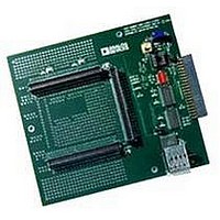
ADZS-21262-1-EZEXT
Description
BOARD DAUGHTER FOR ADSP-21262
Manufacturer
Analog Devices Inc
Datasheet
1.ADSP-21363KSWZ-1AA.pdf
(56 pages)
Specifications of ADZS-21262-1-EZEXT
Accessory Type
DSP
Silicon Manufacturer
Analog Devices
Core Architecture
SHARC
Features
Expansion Interface, High Speed Converter (HSC) Interface
Kit Contents
Board Docs
Silicon Family Name
SHARC
Silicon Core Number
ADSP-21262
Rohs Compliant
Yes
Lead Free Status / RoHS Status
Lead free / RoHS Compliant
For Use With/related Products
ADSP-21262
Lead Free Status / RoHS Status
Lead free / RoHS Compliant, Lead free / RoHS Compliant


generate either center-aligned or edge-aligned PWM wave-
forms. In addition, it can generate complementary signals on
two outputs in paired mode or independent signals in non-
paired mode (applicable to a single group of four PWM
waveforms).
The PWM generator is capable of operating in two distinct
modes while generating center-aligned PWM waveforms: single
update mode or double update mode. In single update mode,
the duty cycle values are programmable only once per PWM
period. This results in PWM patterns that are symmetrical
about the midpoint of the PWM period. In double update
mode, a second updating of the PWM registers is implemented
at the midpoint of the PWM period. In this mode, it is possible
to produce asymmetrical PWM patterns that produce lower
harmonic distortion in 3-phase PWM inverters.
Digital Audio Interface (DAI)
The digital audio interface (DAI) provides the ability to connect
various peripherals to any of the DSP’s DAI pins (DAI_P20–1).
Programs make these connections using the signal routing unit
(SRU, shown in
The SRU is a matrix routing unit (or group of multiplexers) that
enables the peripherals provided by the DAI to be intercon-
nected under software control. This allows easy use of the
DAI-associated peripherals for a wider variety of applications by
using a larger set of algorithms than is possible with nonconfig-
urable signal paths.
The DAI includes six serial ports, an S/PDIF receiver/transmit-
ter, a DTCP cipher, a precision clock generator (PCG), eight
channels of asynchronous sample rate converters, an input data
port (IDP), an SPI port, six flag outputs and six flag inputs, and
three timers. The IDP provides an additional input path to the
ADSP-2136x core, configurable as either eight channels of I
serial data or as seven channels plus a single 20-bit wide syn-
chronous parallel data acquisition port. Each data channel has
its own DMA channel that is independent from the processor’s
serial ports.
Serial Ports
The processor features six synchronous serial ports that provide
an inexpensive interface to a wide variety of digital and mixed-
signal peripheral devices such as Analog Devices’ AD183x fam-
ily of audio codecs, ADCs, and DACs. The serial ports are made
up of two data lines, a clock, and a frame sync. The data lines
can be programmed to either transmit or receive and each data
line has a dedicated DMA channel.
Serial ports are enabled via 12 programmable and simultaneous
receive or transmit pins that support up to 24 transmit or 24
receive channels of audio data when all six SPORTs are enabled,
or six full duplex TDM streams of 128 channels per frame.
Serial port data can be automatically transferred to and from
on-chip memory via dedicated DMA channels. Each of the
serial ports can work in conjunction with another serial port to
provide TDM support. One SPORT provides two transmit sig-
nals while the other SPORT provides the two receive signals.
The frame sync and clock are shared.
Figure
1).
ADSP-21362/ADSP-21363/ADSP-21364/ADSP-21365/ADSP-21366
Rev. G | Page 7 of 56 | March 2011
2
S
Serial ports operate in four modes:
S/PDIF-Compatible Digital Audio Receiver/Transmitter
The S/PDIF transmitter has no separate DMA channels. It
receives audio data in serial format and converts it into a
biphase encoded signal. The serial data input to the transmitter
can be formatted as left-justified, I
word widths of 16, 18, 20, or 24 bits.
The serial data, clock, and frame sync inputs to the S/PDIF
transmitter are routed through the signal routing unit (SRU).
They can come from a variety of sources such as the SPORTs,
external pins, the precision clock generators (PCGs), or the
sample rate converters (SRC) and are controlled by the SRU
control registers.
Digital Transmission Content Protection (DTCP)
The DTCP specification defines a cryptographic protocol for
protecting audio entertainment content from illegal copying,
intercepting, and tampering as it traverses high performance
digital buses, such as the IEEE 1394 standard. Only legitimate
entertainment content delivered to a source device via another
approved copy protection system (such as the DVD content
scrambling system) is protected by this copy protection system.
This feature is available on the ADSP-21362 and
ADSP-21365 processors only. Licensing through DTLA is
required for these products. Visit www.dtcp.com for more
information.
Memory-to-Memory (MTM)
If the DTCP module is not used, the memory-to-memory DMA
module allows internal memory copies for a standard DMA.
Synchronous/Asynchronous Sample Rate Converter (SRC)
The sample rate converter (SRC) contains four SRC blocks and
is the same core as that used in the AD1896 192 kHz stereo
asynchronous sample rate converter and provides up to 140 dB
SNR. The SRC block is used to perform synchronous or
asynchronous sample rate conversion across independent stereo
channels, without using internal processor resources. The four
SRC blocks can also be configured to operate together to con-
vert multichannel audio data without phase mismatches.
Finally, the SRC is used to clean up audio data from jittery clock
sources such as the S/PDIF receiver.
The S/PDIF and SRC are not available on the ADSP-21363
models.
Input Data Port (IDP)
The IDP provides up to eight serial input channels—each with
its own clock, frame sync, and data inputs. The eight channels
are automatically multiplexed into a single 32-bit by eight-deep
FIFO. Data is always formatted as a 64-bit frame and divided
into two 32-bit words. The serial protocol is designed to receive
• Standard DSP serial mode
• Multichannel (TDM) mode
• I
• Left-justified sample pair mode
2
S mode
2
S, or right-justified with
Related parts for ADZS-21262-1-EZEXT
Image
Part Number
Description
Manufacturer
Datasheet
Request
R

Part Number:
Description:
BOARD DAUGHTER EZ EXTENDER
Manufacturer:
Analog Devices Inc
Datasheet:

Part Number:
Description:
±1.7g Dual-Axis IMEMS Accelerometer Evaluation Board
Manufacturer:
Analog Devices Inc
Datasheet:

Part Number:
Description:
Inertial Sensor Evaluation System
Manufacturer:
Analog Devices Inc
Datasheet:
Part Number:
Description:
Manufacturer:
Analog Devices Inc
Datasheet:
Part Number:
Description:
Manufacturer:
Analog Devices Inc
Datasheet:
Part Number:
Description:
Manufacturer:
Analog Devices Inc
Datasheet:
Part Number:
Description:
Manufacturer:
Analog Devices Inc
Datasheet:
Part Number:
Description:
Manufacturer:
Analog Devices Inc
Datasheet:
Part Number:
Description:
Manufacturer:
Analog Devices Inc
Datasheet:
Part Number:
Description:
Manufacturer:
Analog Devices Inc
Datasheet:
Part Number:
Description:
Manufacturer:
Analog Devices Inc
Datasheet:
Part Number:
Description:
Manufacturer:
Analog Devices Inc
Datasheet:
Part Number:
Description:
Manufacturer:
Analog Devices Inc
Datasheet: