ADZS-21262-1-EZEXT Analog Devices Inc, ADZS-21262-1-EZEXT Datasheet - Page 44
ADZS-21262-1-EZEXT
Manufacturer Part Number
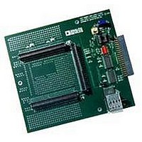
ADZS-21262-1-EZEXT
Description
BOARD DAUGHTER FOR ADSP-21262
Manufacturer
Analog Devices Inc
Datasheet
1.ADSP-21363KSWZ-1AA.pdf
(56 pages)
Specifications of ADZS-21262-1-EZEXT
Accessory Type
DSP
Silicon Manufacturer
Analog Devices
Core Architecture
SHARC
Features
Expansion Interface, High Speed Converter (HSC) Interface
Kit Contents
Board Docs
Silicon Family Name
SHARC
Silicon Core Number
ADSP-21262
Rohs Compliant
Yes
Lead Free Status / RoHS Status
Lead free / RoHS Compliant
For Use With/related Products
ADSP-21262
Lead Free Status / RoHS Status
Lead free / RoHS Compliant, Lead free / RoHS Compliant


ADSP-21362/ADSP-21363/ADSP-21364/ADSP-21365/ADSP-21366
OUTPUT DRIVE CURRENTS
Figure 37
ers of the processor. The curves represent the current drive
capability of the output drivers as a function of output voltage.
TEST CONDITIONS
The ac signal specifications (timing parameters) appear in
Table 12 on Page 19
output disable time, output enable time, and capacitive loading.
The timing specifications for the SHARC apply for the voltage
reference levels in
Timing is measured on signals when they cross the 1.5 V level as
described in
sured between the point that the first signal reaches 1.5 V and
the point that the second signal reaches 1.5 V.
- 20
- 30
- 40
- 10
40
30
20
10
Figure 38. Equivalent Device Loading for AC Measurements
Figure 39. Voltage Reference Levels for AC Measurements
0
OUTPUT
0
INPUT
shows typical I-V characteristics for the output driv-
OR
Figure
V OL
OUTPUT
0.5
1.5V
Figure 37. ADSP-2136x Typical Drive
PIN
TO
Figure
39. All delays (in nanoseconds) are mea-
through
3.47V, - 45°C
SWEEP (V
1.0
(Includes All Fixtures)
38.
3.11V, +125°C
Table 41 on Page
1.5
DDEXT
30pF
) VOLTAGE (V)
V OH
2.0
3.11V, +125°C
2.5
3.3V, +25°C
V
LOAD
43. These include
3.0
Rev. G | Page 44 of 56 | March 2011
1.5V
3.47V, - 45°C
3.3V, +25°C
3.5
CAPACITIVE LOADING
Output delays and holds are based on standard capacitive loads:
30 pF on all pins (see
how output delays and holds vary with load capacitance. The
graphs of
outside the ranges shown for Typical Output Delay versus Load
Capacitance and Typical Output Rise Time (20% to 80%,
V = Min) versus Load Capacitance.
12
10
Figure
12
10
0
8
6
4
2
8
6
4
2
0
0
0
Figure 40. Typical Output Rise/Fall Time
Figure 41. Typical Output Rise/Fall Time
40,
y = 0.0467x + 1.6323
Figure
(20% to 80%, V
(20% to 80%, V
50
50
Figure
y = 0.049x + 1.5105
LOAD CAPACITANCE (pF)
41, and
LOAD CAPACITANCE (pF)
38).
100
100
y = 0.045x + 1.524
Figure 42
y = 0.0482x + 1.4604
DDEXT
DDEXT
Figure 42
= Max)
= Min)
RISE
150
150
RISE
shows graphically
FALL
FALL
may not be linear
200
200
250
250
Related parts for ADZS-21262-1-EZEXT
Image
Part Number
Description
Manufacturer
Datasheet
Request
R

Part Number:
Description:
BOARD DAUGHTER EZ EXTENDER
Manufacturer:
Analog Devices Inc
Datasheet:

Part Number:
Description:
±1.7g Dual-Axis IMEMS Accelerometer Evaluation Board
Manufacturer:
Analog Devices Inc
Datasheet:

Part Number:
Description:
Inertial Sensor Evaluation System
Manufacturer:
Analog Devices Inc
Datasheet:
Part Number:
Description:
Manufacturer:
Analog Devices Inc
Datasheet:
Part Number:
Description:
Manufacturer:
Analog Devices Inc
Datasheet:
Part Number:
Description:
Manufacturer:
Analog Devices Inc
Datasheet:
Part Number:
Description:
Manufacturer:
Analog Devices Inc
Datasheet:
Part Number:
Description:
Manufacturer:
Analog Devices Inc
Datasheet:
Part Number:
Description:
Manufacturer:
Analog Devices Inc
Datasheet:
Part Number:
Description:
Manufacturer:
Analog Devices Inc
Datasheet:
Part Number:
Description:
Manufacturer:
Analog Devices Inc
Datasheet:
Part Number:
Description:
Manufacturer:
Analog Devices Inc
Datasheet:
Part Number:
Description:
Manufacturer:
Analog Devices Inc
Datasheet: