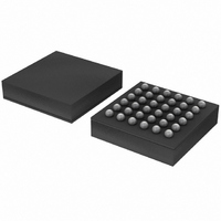
SC16C852SVIET,115 NXP Semiconductors, SC16C852SVIET,115 Datasheet - Page 35

SC16C852SVIET,115
Manufacturer Part Number
SC16C852SVIET,115
Description
IC UART DL 1.8V W/FIFO 36-TFBGA
Manufacturer
NXP Semiconductors
Datasheet
1.SC16C852SVIET151.pdf
(48 pages)
Specifications of SC16C852SVIET,115
Features
Programmable
Number Of Channels
2, DUART
Fifo's
128 Byte
Protocol
RS485
Voltage - Supply
1.8V
With Auto Flow Control
Yes
With Irda Encoder/decoder
Yes
With False Start Bit Detection
Yes
With Modem Control
Yes
With Cmos
Yes
Mounting Type
Surface Mount
Package / Case
36-TFBGA
Lead Free Status / RoHS Status
Lead free / RoHS Compliant
Other names
935286451115
SC16C852SVIET-G
SC16C852SVIET-G
SC16C852SVIET-G
SC16C852SVIET-G
Available stocks
Company
Part Number
Manufacturer
Quantity
Price
Company:
Part Number:
SC16C852SVIET,115
Manufacturer:
NXP Semiconductors
Quantity:
10 000
NXP Semiconductors
SC16C852SV_1
Product data sheet
7.23 Advanced Feature Control Register 2 (AFCR2)
Table 32.
[1]
Table 33.
Bit
1
0
Bit
7:6
5
4
3
2
1
0
It takes 4 XTAL1 clocks to reset the device.
Symbol
AFCR2[7:6]
AFCR2[5]
AFCR2[4]
AFCR2[3]
AFCR2[2]
AFCR2[1]
AFCR2[0]
Symbol
AFCR1[1]
AFCR1[0]
Advanced Feature Control Register 1 bits description
Advanced Feature Control Register 2 bits description
Dual UART with 128-byte FIFOs, IrDA, and XScale VLIO bus interface
Rev. 01 — 23 September 2008
Description
SReset. Software reset. A write to this bit will reset the UART. Once the
UART is reset this bit is automatically set to 0.
TSR interrupt. Select TSR interrupt mode.
Description
reserved
RTSInvert. Invert RTS or DTR signal in auto 9-bit mode.
RTSCon. Enable the transmitter to control RTS or DTR signal in auto 9-bit
mode.
RS485 RTS/DTR. Select RTSA/RTSB or DTRA/DTRB pin to control the
external transceiver.
TXDisable. Disable transmitter.
RXDisable. Disable receiver.
9-bitMode. Enable 9-bit mode or Multidrop (RS-485) mode.
0 = transmit empty interrupt occurs when transmit FIFO falls below the
trigger level or becomes empty.
1 = transmit empty interrupt occurs when transmit FIFO fall below the
trigger level, or becomes empty and the last stop bit has been shift out
the transmit shift register.
0 = RTS or DTR is set to 0 by the UART during transmission, and to 1
during reception
1 = RTS or DTR is set to 1 by the UART during transmission, and to 0
during reception
0 = transmitter does not control RTS or DTR signal
1 = transmitter controls RTS or DTR signal
0 = RTSA/RTSB pin is used to control the external transceiver
1 = DTRA/DTRB pin is used to control the external transceiver
0 = transmitter is enabled
1 = transmitter is disabled
0 = receiver is enabled
1 = receiver is disabled
0 = normal RS-232 mode
1 = enable 9-bit mode
SC16C852SV
[1]
…continued
© NXP B.V. 2008. All rights reserved.
35 of 48


