SC16C852SVIET,115 NXP Semiconductors, SC16C852SVIET,115 Datasheet - Page 10
SC16C852SVIET,115
Manufacturer Part Number
SC16C852SVIET,115
Description
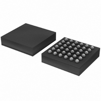
IC UART DL 1.8V W/FIFO 36-TFBGA
Manufacturer
NXP Semiconductors
Datasheet
1.SC16C852SVIET151.pdf
(48 pages)
Specifications of SC16C852SVIET,115
Features
Programmable
Number Of Channels
2, DUART
Fifo's
128 Byte
Protocol
RS485
Voltage - Supply
1.8V
With Auto Flow Control
Yes
With Irda Encoder/decoder
Yes
With False Start Bit Detection
Yes
With Modem Control
Yes
With Cmos
Yes
Mounting Type
Surface Mount
Package / Case
36-TFBGA
Lead Free Status / RoHS Status
Lead free / RoHS Compliant
Other names
935286451115
SC16C852SVIET-G
SC16C852SVIET-G
SC16C852SVIET-G
SC16C852SVIET-G
Available stocks
Company
Part Number
Manufacturer
Quantity
Price
Company:

Part Number:
SC16C852SVIET,115
Manufacturer:
NXP Semiconductors
Quantity:
10 000


NXP Semiconductors
SC16C852SV_1
Product data sheet
6.6 Software flow control
SC16C852SV will suspend TX transmissions as soon as the stop bit of the character in
process is shifted out. Transmission is resumed after the CTSx input returns to a logic 0,
indicating more data may be sent.
When AFCR1[2] is set to 1, then the function of CTSx pin is mapped to the DSRx pin, and
the function of RTS is mapped to DTRx pin. DSRx and DTRx pins will behave as
described above for CTSx and RTSx.
With the automatic hardware flow control function enabled, an interrupt is generated when
the receive FIFO reaches the programmed trigger level. The RTSx (or DTRx) pin will not
be forced to a logic 1 (RTS off) until the receive FIFO reaches the next trigger level.
However, the RTSx (or DTRx) pin will return to a logic 0 after the receive buffer (FIFO) is
unloaded to the next trigger level below the programmed trigger level. Under the above
described conditions, the SC16C852SV will continue to accept data until the receive FIFO
is full.
When TXINTLVL, RXINTLVL, FLWCNTH and FLWCNTL in the First Extra Register Set
are all zeroes, the hardware and software flow control trigger levels are set by FCR[7:4];
see
When either TXINTLVL, RXINTLVL, FLWCNTH or FLWCNTL in the First Extra Register
Set contains any value other than 0x00, the hardware and software flow control trigger
levels are set by FLWCNTH and FLWCNTL. The content in FLWCNTH determines how
many bytes are in the receive FIFO before RTSx (or DTRx) is de-asserted or XOFF is
sent. The content of FLWCNTL determines how many bytes are in the receive FIFO
before RTSx (or DTRx) is asserted, or XON is sent.
In 128-byte FIFO mode, hardware and software flow control trigger levels can be set to
any value between 1 and 128 in granularity of 1. The value of FLWCNTH should always
be greater than FLWCNTL. The UART does not check for this condition automatically, and
if this condition is not met spurious operation of the device might occur. When using
FLWCNTH and FWLCNTL, these registers must be initialized to the proper values before
hardware or software flow control is enabled via the EFR register.
When software flow control is enabled, the SC16C852SV compares one or two
sequentially received data characters with the programmed Xon or Xoff character
value(s). If the received character(s) match the programmed Xoff values, the
SC16C852SV will halt transmission (TX) as soon as the current character(s) has
completed transmission. When a match occurs, ISR bit 4 will be set (if enabled via IER[5])
and the interrupt output pin (if receive interrupt is enabled) will be activated. Following a
suspension due to a match of the Xoff characters’ values, the SC16C852SV will monitor
the receive data stream for a match to the Xon1/Xon2 character value(s). If a match is
found, the SC16C852SV will resume operation and clear the flags (ISR[4]).
Reset initially sets the contents of the Xon/Xoff 8-bit flow control registers to a logic 0.
Following reset, the user can write any Xon/Xoff value desired for software flow control.
Different conditions can be set to detect Xon/Xoff characters and suspend/resume
transmissions (see
SC16C852SV compares two consecutive receive characters with two software flow
control 8-bit values (Xon1, Xon2, Xoff1, Xoff2) and controls TX transmissions accordingly.
Table
5.
Dual UART with 128-byte FIFOs, IrDA, and XScale VLIO bus interface
Table
Rev. 01 — 23 September 2008
24). When double 8-bit Xon/Xoff characters are selected, the
SC16C852SV
© NXP B.V. 2008. All rights reserved.
10 of 48
Related parts for SC16C852SVIET,115
Image
Part Number
Description
Manufacturer
Datasheet
Request
R

Part Number:
Description:
NXP Semiconductors designed the LPC2420/2460 microcontroller around a 16-bit/32-bitARM7TDMI-S CPU core with real-time debug interfaces that include both JTAG andembedded trace
Manufacturer:
NXP Semiconductors
Datasheet:

Part Number:
Description:
NXP Semiconductors designed the LPC2458 microcontroller around a 16-bit/32-bitARM7TDMI-S CPU core with real-time debug interfaces that include both JTAG andembedded trace
Manufacturer:
NXP Semiconductors
Datasheet:
Part Number:
Description:
NXP Semiconductors designed the LPC2468 microcontroller around a 16-bit/32-bitARM7TDMI-S CPU core with real-time debug interfaces that include both JTAG andembedded trace
Manufacturer:
NXP Semiconductors
Datasheet:
Part Number:
Description:
NXP Semiconductors designed the LPC2470 microcontroller, powered by theARM7TDMI-S core, to be a highly integrated microcontroller for a wide range ofapplications that require advanced communications and high quality graphic displays
Manufacturer:
NXP Semiconductors
Datasheet:
Part Number:
Description:
NXP Semiconductors designed the LPC2478 microcontroller, powered by theARM7TDMI-S core, to be a highly integrated microcontroller for a wide range ofapplications that require advanced communications and high quality graphic displays
Manufacturer:
NXP Semiconductors
Datasheet:
Part Number:
Description:
The Philips Semiconductors XA (eXtended Architecture) family of 16-bit single-chip microcontrollers is powerful enough to easily handle the requirements of high performance embedded applications, yet inexpensive enough to compete in the market for hi
Manufacturer:
NXP Semiconductors
Datasheet:
Part Number:
Description:
The XA-S3 device is a member of Philips Semiconductors? XA(eXtended Architecture) family of high performance 16-bitsingle-chip microcontrollers
Manufacturer:
NXP Semiconductors
Datasheet:

Part Number:
Description:
The NXP BlueStreak LH75401/LH75411 family consists of two low-cost 16/32-bit System-on-Chip (SoC) devices
Manufacturer:
NXP Semiconductors
Datasheet:
Part Number:
Description:
The NXP LPC3130/3131 combine an 180 MHz ARM926EJ-S CPU core, high-speed USB2
Manufacturer:
NXP Semiconductors
Datasheet:
Part Number:
Description:
The NXP LPC3141 combine a 270 MHz ARM926EJ-S CPU core, High-speed USB 2
Manufacturer:
NXP Semiconductors
Part Number:
Description:
The NXP LPC3143 combine a 270 MHz ARM926EJ-S CPU core, High-speed USB 2
Manufacturer:
NXP Semiconductors

Part Number:
Description:
The NXP LPC3152 combines an 180 MHz ARM926EJ-S CPU core, High-speed USB 2
Manufacturer:
NXP Semiconductors
Part Number:
Description:
The NXP LPC3154 combines an 180 MHz ARM926EJ-S CPU core, High-speed USB 2
Manufacturer:
NXP Semiconductors

Part Number:
Description:
Standard level N-channel enhancement mode Field-Effect Transistor (FET) in a plastic package using NXP High-Performance Automotive (HPA) TrenchMOS technology
Manufacturer:
NXP Semiconductors
Datasheet: