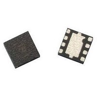
ATF-521P8-TR1 Avago Technologies US Inc., ATF-521P8-TR1 Datasheet - Page 21

ATF-521P8-TR1
Manufacturer Part Number
ATF-521P8-TR1
Description
IC PHEMT 2GHZ 4.5V 200MA 8-LPCC
Manufacturer
Avago Technologies US Inc.
Datasheet
1.ATF-521P8-BLK.pdf
(23 pages)
Specifications of ATF-521P8-TR1
Gain
17dB
Transistor Type
pHEMT FET
Frequency
2GHz
Voltage - Rated
7V
Current Rating
500mA
Noise Figure
1.5dB
Current - Test
200mA
Voltage - Test
4.5V
Power - Output
26.5dBm
Package / Case
8-LPCC
Power Dissipation Pd
1.5W
Rf Transistor Case
LPCC
No. Of Pins
8
Frequency Max
6GHz
Noise Figure Typ
1.5dB
Frequency Min
50MHz
Continuous Drain Current Id
14.8µA
Configuration
Single Dual Source
Drain-gate Voltage (max)
-5 to 1V
Operating Temperature (max)
150C
Operating Temperature Classification
Military
Mounting
Surface Mount
Drain Current Idss Max
200mA
Drain Source Voltage Vds
4.5V
Rohs Compliant
Yes
Lead Free Status / RoHS Status
Lead free / RoHS Compliant
Lead Free Status / RoHS Status
Lead free / RoHS Compliant, Lead free / RoHS Compliant
Available stocks
Company
Part Number
Manufacturer
Quantity
Price
Company:
Part Number:
ATF-521P8-TR1
Manufacturer:
AVAGO
Quantity:
12 367
Company:
Part Number:
ATF-521P8-TR1
Manufacturer:
LATTICE
Quantity:
9
Part Number:
ATF-521P8-TR1
Manufacturer:
AGILENT
Quantity:
20 000
Company:
Part Number:
ATF-521P8-TR1G
Manufacturer:
AVAGO
Quantity:
10 000
Part Number:
ATF-521P8-TR1G
Manufacturer:
AVAGO/安华高
Quantity:
20 000
Thus, for reliable operation of ATF‑521P8 and extended
MTBF, it is recommended to use some form of thermal
heatsinking. This may include any or all of the following
suggestions:
• Maximize vias underneath and around package;
• Maximize exposed surface metal;
• Use 1 oz or greater copper clad;
• Minimize board thickness;
• Metal heat sinks or extrusions;
• Fans or forced air;
• Mount PCB to Chassis.
Summary
A high linearity Tx driver amplifier for WCDMA has been
presented and designed using Agilent’s ATF‑521P8. This
includes RF, DC and good thermal dissipation practices
for reliable lifetime operation. A summary of the typical
performance for ATF‑521P8 demoboard at 2140 MHz is
as follows:
Demo Board Results at 2140 MHz
Gain
OIP3
ACLR
P1dB
NF
2 x 2 LPCC (JEDEC DFP-N) Package Dimensions
21
A
E1
A1
L
End View
Bottom View
R
D1
P
16.5 dB
41.2 dBm
‑58 dBc
24.8 dBm
1.55 dB
A2
b
e
pin1
pin1
1
2
3
4
Top View
End View
2PX
D
References
[1] Ward, A. (2001) Avago Technologies ATF-54143 Low Noise
Enhancement Mode Pseudomorphic HEMT in a Surface Mount Plastic
Package, 2001 [Internet], Available from:
<http://www.avagotech.com>
[2] Biasing Circuits and Considerations for GaAs MESFET
Power Amplifiers, 2001 [Internet], Available from:
<http://www.rf‑solutions.com/pdf/AN‑0002_ajp.pdf>
[Accessed 22 August, 2002]
Device Models
Refer to Avago Technologies' Web Site:
www.avagotech.com
Ordering Information
Part Number
ATF‑521P8‑TR1
ATF‑521P8‑TR2
ATF‑521P8‑BLK
8
7
6
5
A
E
No. of Devices
DIMENSIONS ARE IN MILLIMETERS
SYMBOL
A1
A2
D1
E1
A
D
P
b
E
e
L
3000
10000
100
0.225
MIN.
0.70
0.65
1.45
0.35
1.9
1.9
0.2
Container
0
DIMENSIONS
0.203 REF
0.50 BSC
NOM.
0.25
0.75
0.02
0.25
0.80
0.4
2.0
2.0
1.6
7” Reel
13”Reel
antistatic bag
MAX.
0.275
0.80
0.05
0.95
1.75
0.45
2.1
2.1
0.3


