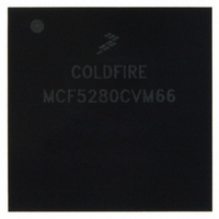
MCF5280CVM66 Freescale Semiconductor, MCF5280CVM66 Datasheet - Page 575

MCF5280CVM66
Manufacturer Part Number
MCF5280CVM66
Description
IC MPU 32BIT COLDF 256-MAPBGA
Manufacturer
Freescale Semiconductor
Series
MCF528xr
Datasheet
1.MCF5216CVM66J.pdf
(766 pages)
Specifications of MCF5280CVM66
Core Processor
Coldfire V2
Core Size
32-Bit
Speed
66MHz
Connectivity
CAN, EBI/EMI, Ethernet, I²C, SPI, UART/USART
Peripherals
DMA, LVD, POR, PWM, WDT
Number Of I /o
142
Program Memory Type
ROMless
Ram Size
64K x 8
Voltage - Supply (vcc/vdd)
2.7 V ~ 3.6 V
Data Converters
A/D 8x10b
Oscillator Type
External
Operating Temperature
-40°C ~ 85°C
Package / Case
256-MAPBGA
Controller Family/series
ColdFire
No. Of I/o's
150
Program Memory Size
2KB
Ram Memory Size
64KB
Cpu Speed
66.67MHz
Embedded Interface Type
CAN, I2C, SPI, UART
No. Of Pwm Channels
8
Rohs Compliant
Yes
Lead Free Status / RoHS Status
Lead free / RoHS Compliant
Eeprom Size
-
Program Memory Size
-
Available stocks
Company
Part Number
Manufacturer
Quantity
Price
Company:
Part Number:
MCF5280CVM66
Manufacturer:
FREESCAL
Quantity:
151
Company:
Part Number:
MCF5280CVM66
Manufacturer:
Freescale Semiconductor
Quantity:
10 000
Company:
Part Number:
MCF5280CVM66J
Manufacturer:
Freescale Semiconductor
Quantity:
10 000
Company:
Part Number:
MCF5280CVM66L
Manufacturer:
FREESCAL
Quantity:
151
- Current page: 575 of 766
- Download datasheet (9Mb)
The following paragraphs and figures outline the prioritizing criteria used to determine which conversion
occurs in each overlap situation.
Trigger events are described in
When a trigger event causes a CCW execution in progress to be aborted, the aborted conversion is shown
as a ragged end of a shortened CCW rectangle.
The situation diagrams also show when key status bits are set.
Table 28-23
Below the queue execution flows are three sets of blocks that show the status information that is made
available to the user. The first two rows of status blocks show the condition of each queue as:
The third row of status blocks shows the 4-bit QS status register field that encodes the condition of the two
queues. Two transition status cases, QS = 0011 and QS = 0111, are not shown because they exist only very
briefly between stable status conditions.
Freescale Semiconductor
•
•
•
•
•
Idle
Active
Pause
Suspended (queue 2 only)
Trigger pending
describes the status bits.
Trigger
Each situation in
S19. In each diagram, time is shown increasing from left to right. The
execution of queue 1 and queue 2 (Q1 and Q2) is shown as a string of
rectangles representing the execution time of each CCW in the queue. In
most of the situations, there are four CCWs (labeled C1 to C4) in both queue
1 and queue 2. In some of the situations, CCW C2 is presumed to have the
pause bit set, to show the similarities of pause and end-of-queue as
terminations of queue execution.
Trigger overrun
T1
T2
error (TOR)
CF flag
PF flag
Bit
Events that trigger queue 1 execution (external trigger, software-initiated single-scan
enable bit, or completion of the previous continuous loop)
Events that trigger queue 2 execution (external trigger, software-initiated single-scan
enable bit, timer period/interval expired, or completion of the previous continuous
loop)
MCF5282 and MCF5216 ColdFire Microcontroller User’s Manual, Rev. 3
Table
Set when the end of the queue is reached
Set when a queue completes execution up through a pause bit
Set when a new trigger event occurs before the queue is finished
servicing the previous trigger event
Figure 28-23
28-22.
Table 28-22. Trigger Events
Table 28-23. Status Bits
through
NOTE
Events
Figure 28-33
Function
is labeled S1 through
Queued Analog-to-Digital Converter (QADC)
28-37
Related parts for MCF5280CVM66
Image
Part Number
Description
Manufacturer
Datasheet
Request
R
Part Number:
Description:
Manufacturer:
Freescale Semiconductor, Inc
Datasheet:
Part Number:
Description:
Manufacturer:
Freescale Semiconductor, Inc
Datasheet:
Part Number:
Description:
Manufacturer:
Freescale Semiconductor, Inc
Datasheet:
Part Number:
Description:
Manufacturer:
Freescale Semiconductor, Inc
Datasheet:
Part Number:
Description:
Manufacturer:
Freescale Semiconductor, Inc
Datasheet:
Part Number:
Description:
Manufacturer:
Freescale Semiconductor, Inc
Datasheet:
Part Number:
Description:
Manufacturer:
Freescale Semiconductor, Inc
Datasheet:
Part Number:
Description:
Manufacturer:
Freescale Semiconductor, Inc
Datasheet:
Part Number:
Description:
Manufacturer:
Freescale Semiconductor, Inc
Datasheet:
Part Number:
Description:
Manufacturer:
Freescale Semiconductor, Inc
Datasheet:
Part Number:
Description:
Manufacturer:
Freescale Semiconductor, Inc
Datasheet:
Part Number:
Description:
Manufacturer:
Freescale Semiconductor, Inc
Datasheet:
Part Number:
Description:
Manufacturer:
Freescale Semiconductor, Inc
Datasheet:
Part Number:
Description:
Manufacturer:
Freescale Semiconductor, Inc
Datasheet:
Part Number:
Description:
Manufacturer:
Freescale Semiconductor, Inc
Datasheet:


