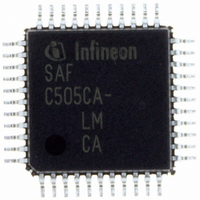
SAF-C515C-8EM CA Infineon Technologies, SAF-C515C-8EM CA Datasheet - Page 73

SAF-C515C-8EM CA
Manufacturer Part Number
SAF-C515C-8EM CA
Description
IC MCU 8BIT OTP MQFP-80-1
Manufacturer
Infineon Technologies
Series
C5xx/C8xxr
Datasheet
1.SAF-C515C-8EM_CA.pdf
(96 pages)
Specifications of SAF-C515C-8EM CA
Core Processor
C500
Core Size
8-Bit
Speed
10MHz
Connectivity
CAN, EBI/EMI, SPI, UART/USART
Peripherals
POR, PWM, WDT
Number Of I /o
49
Program Memory Size
64KB (64K x 8)
Program Memory Type
OTP
Ram Size
2.5K x 8
Voltage - Supply (vcc/vdd)
4.25 V ~ 5.5 V
Data Converters
A/D 8x10b
Oscillator Type
External
Operating Temperature
-40°C ~ 85°C
Package / Case
80-SQFP
Data Bus Width
8 bit
Data Ram Size
2.25 KB
Interface Type
USART, SSC
Maximum Clock Frequency
10 MHz
Number Of Programmable I/os
49
Number Of Timers
3
Operating Supply Voltage
5 V
Maximum Operating Temperature
+ 85 C
Mounting Style
SMD/SMT
Minimum Operating Temperature
- 40 C
On-chip Adc
10 bit, 8 Channel
Packages
PG-MQFP-80
Max Clock Frequency
10.0 MHz
Sram (incl. Cache)
2.25 KByte
Can Nodes
1
A / D Input Lines (incl. Fadc)
8
Program Memory
64.0 KByte
Lead Free Status / RoHS Status
Lead free / RoHS Compliant
Eeprom Size
-
Lead Free Status / Rohs Status
Details
Other names
F515C8EMCANP
F515C8EMCAXT
SAF-C515C-8EMCA
SAF-C515C-8EMCA
SAF-C515C-8EMCAIN
SAFC515C8EMCAX
SP000068749
SP000106399
F515C8EMCAXT
SAF-C515C-8EMCA
SAF-C515C-8EMCA
SAF-C515C-8EMCAIN
SAFC515C8EMCAX
SP000068749
SP000106399
Power Supply Current
Parameter
Active mode
Idle mode
Active mode
with slow-down
enabled
Idle mode with
slow-down
enabled
Power-down
mode
At EA/
programming
mode
1)
2)
3)
4)
5)
Data Sheet
The typical
The maximum
I
XTAL2 driven with
EA = PE/SWD = Port 0 = Port 6 =
I
XTAL2 driven with
RESET =
I
disabled;
XTAL2 driven with
RESET =
DD
DD
DD
(active mode with slow-down mode) is measured with all output pins disconnected and with all peripherals
(active mode) is measured with:
(idle mode) is measured with all output pins disconnected and with all peripherals disabled;
V
PP
V
V
in
I
DD
DD
DD
; EA =
; all other pins are disconnected; the microcontroller is put into slow-down mode by software.
I
values are periodically measured at
DD
C515C-8R/
C515C-LM
C515C-8E
C515C-8R/
C515C-LM
C515C-8E
C515C-8R/
C515C-LM
C515C-8E
C515C-8R/
C515C-LM
C515C-8E
C515C-8R/
C515C-LM
C515C-8E
C515C-8E
values are measured under worst case conditions (
t
t
t
CLCH
CLCH
CLCH
V
SS
,
,
,
; Port0 =
t
t
t
CHCL
CHCL
CHCL
= 5 ns,
= 5 ns,
= 5 ns,
V
V
6 MHz
10 MHz
6 MHz
10 MHz
6 MHz
10 MHz
6 MHz
10 MHz
6 MHz
10 MHz
6 MHz
10 MHz
6 MHz
10 MHz
6 MHz
10 MHz
DD
DD
; all other pins are disconnected;
; HWPD =
V
V
V
IL
IL
IL
=
=
=
V
V
V
SS
SS
SS
Sym-
bol
I
I
I
I
I
I
I
I
I
I
I
DD
DD
DD
DD
DD
DD
DD
DD
PD
PD
DDP
V
+ 0.5 V,
+ 0.5 V,
+ 0.5 V,
DD
69
T
A
; RESET =
= +25 C and
typ.
11.97
18.81
11.3
17.66
6.9
10.46
3.95
4.71
4.06
4.62
4.01
4.65
3.54
3.86
3.62
4.14
26
11.14
–
Limit Values
V
V
V
IH
IH
IH
1)
=
=
=
V
V
V
V
DD
DD
DD
SS
max.
13.74
21.10
12.94
20.10
7.87
11.87
4.70
5.50
5.03
5.75
4.77
5.53
4.46
4.90
4.21
4.77
42.9
30
30
; all other pins are disconnected.
- 0.5 V; XTAL1 = N.C.;
- 0.5 V; XTAL1 = N.C.;
- 0.5 V; XTAL1 = N.C.;
V
T
DD
A
= 0 C or -40 C and
2)
= 5 V but not 100% tested.
Unit Test Condition
mA
mA
mA
mA
mA
mA
mA
mA
mA
A
A
3)
4)
5)
6)
V
7)
–
DD
= 2 … 5.5 V
V
DD
C515C
2003-02
= 5.5 V)


