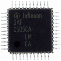
SAF-C515C-8EM CA Infineon Technologies, SAF-C515C-8EM CA Datasheet - Page 38

SAF-C515C-8EM CA
Manufacturer Part Number
SAF-C515C-8EM CA
Description
IC MCU 8BIT OTP MQFP-80-1
Manufacturer
Infineon Technologies
Series
C5xx/C8xxr
Datasheet
1.SAF-C515C-8EM_CA.pdf
(96 pages)
Specifications of SAF-C515C-8EM CA
Core Processor
C500
Core Size
8-Bit
Speed
10MHz
Connectivity
CAN, EBI/EMI, SPI, UART/USART
Peripherals
POR, PWM, WDT
Number Of I /o
49
Program Memory Size
64KB (64K x 8)
Program Memory Type
OTP
Ram Size
2.5K x 8
Voltage - Supply (vcc/vdd)
4.25 V ~ 5.5 V
Data Converters
A/D 8x10b
Oscillator Type
External
Operating Temperature
-40°C ~ 85°C
Package / Case
80-SQFP
Data Bus Width
8 bit
Data Ram Size
2.25 KB
Interface Type
USART, SSC
Maximum Clock Frequency
10 MHz
Number Of Programmable I/os
49
Number Of Timers
3
Operating Supply Voltage
5 V
Maximum Operating Temperature
+ 85 C
Mounting Style
SMD/SMT
Minimum Operating Temperature
- 40 C
On-chip Adc
10 bit, 8 Channel
Packages
PG-MQFP-80
Max Clock Frequency
10.0 MHz
Sram (incl. Cache)
2.25 KByte
Can Nodes
1
A / D Input Lines (incl. Fadc)
8
Program Memory
64.0 KByte
Lead Free Status / RoHS Status
Lead free / RoHS Compliant
Eeprom Size
-
Lead Free Status / Rohs Status
Details
Other names
F515C8EMCANP
F515C8EMCAXT
SAF-C515C-8EMCA
SAF-C515C-8EMCA
SAF-C515C-8EMCAIN
SAFC515C8EMCAX
SP000068749
SP000106399
F515C8EMCAXT
SAF-C515C-8EMCA
SAF-C515C-8EMCA
SAF-C515C-8EMCAIN
SAFC515C8EMCAX
SP000068749
SP000106399
Timer / Counter 0 and 1
Timer / Counter 0 and 1 can be used in four operating modes as listed in
Table 7
Mode
0
1
2
3
In the “timer” function (C/
Therefore the count rate is
In the “counter” function the register is incremented in response to a 1-to-0 transition at
its corresponding external input pin (P3.4/T0, P3.5/T1). Since it takes two machine
cycles to detect a falling edge the max. count rate is
INT1
measurements.
Figure 11
Data Sheet
(P3.2, P3.3) can be programmed to function as a gate to facilitate pulse width
Description
8-bit timer/counter with a
divide-by-32 prescaler
16-bit timer/counter
8-bit timer/counter with 8-bit
autoreload
Timer/counter 0 used as
one 8-bit timer/counter and
one 8-bit timer / Timer 1
stops
Timer/Counter 0 and 1 Operating Modes
Timer/Counter 0 and 1 Input Clock Logic
P3.4/T0
P3.5/T1
Gate
(TMOD)
P3.2/INT0
P3.3/INT1
Figure 11
T
illustrates the input clock logic.
f
=1
OSC
OSC
= ‘0’) the register is incremented every machine cycle.
/6.
÷
<
_
M1
0
0
1
1
6
1
TMOD
TR0
TR1
34
M0
0
1
0
1
C/T = 0
C/T = 1
&
internal
f
f
OSC
OSC
f
OSC
Timer/Counter Input Clock
/6
/6
Control
/12. External inputs
32
f
Timer 0/1
Input Clock
OSC
MCS03117
/6
external (max)
f
f
OSC
OSC
Table
/12
/12
INT0
C515C
2003-02
7:
32
and


