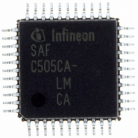
SAF-C515C-8EM CA Infineon Technologies, SAF-C515C-8EM CA Datasheet - Page 48

SAF-C515C-8EM CA
Manufacturer Part Number
SAF-C515C-8EM CA
Description
IC MCU 8BIT OTP MQFP-80-1
Manufacturer
Infineon Technologies
Series
C5xx/C8xxr
Datasheet
1.SAF-C515C-8EM_CA.pdf
(96 pages)
Specifications of SAF-C515C-8EM CA
Core Processor
C500
Core Size
8-Bit
Speed
10MHz
Connectivity
CAN, EBI/EMI, SPI, UART/USART
Peripherals
POR, PWM, WDT
Number Of I /o
49
Program Memory Size
64KB (64K x 8)
Program Memory Type
OTP
Ram Size
2.5K x 8
Voltage - Supply (vcc/vdd)
4.25 V ~ 5.5 V
Data Converters
A/D 8x10b
Oscillator Type
External
Operating Temperature
-40°C ~ 85°C
Package / Case
80-SQFP
Data Bus Width
8 bit
Data Ram Size
2.25 KB
Interface Type
USART, SSC
Maximum Clock Frequency
10 MHz
Number Of Programmable I/os
49
Number Of Timers
3
Operating Supply Voltage
5 V
Maximum Operating Temperature
+ 85 C
Mounting Style
SMD/SMT
Minimum Operating Temperature
- 40 C
On-chip Adc
10 bit, 8 Channel
Packages
PG-MQFP-80
Max Clock Frequency
10.0 MHz
Sram (incl. Cache)
2.25 KByte
Can Nodes
1
A / D Input Lines (incl. Fadc)
8
Program Memory
64.0 KByte
Lead Free Status / RoHS Status
Lead free / RoHS Compliant
Eeprom Size
-
Lead Free Status / Rohs Status
Details
Other names
F515C8EMCANP
F515C8EMCAXT
SAF-C515C-8EMCA
SAF-C515C-8EMCA
SAF-C515C-8EMCAIN
SAFC515C8EMCAX
SP000068749
SP000106399
F515C8EMCAXT
SAF-C515C-8EMCA
SAF-C515C-8EMCA
SAF-C515C-8EMCAIN
SAFC515C8EMCAX
SP000068749
SP000106399
C515C
The Cyclic Redundancy Check Register (CRC) generates the Cyclic Redundancy
Check code to be transmitted after the data bytes and checks the CRC code of incoming
messages. This is done by dividing the data stream by the code generator polynomial.
The Error Management Logic (EML) is responsible for the fault confinement of the
CAN device. Its counters, the Receive Error Counter and the Transmit Error Counter, are
incremented and decremented by commands from the Bit Stream Processor. According
to the values of the error counters, the CAN controller is set into the states error active,
error passive and busoff.
The Bit Timing Logic (BTL) monitors the busline input RXDC and handles the busline
related bit timing according to the CAN protocol. The BTL synchronizes on a recessive
to dominant busline transition at Start of Frame (hard synchronization) and on any further
recessive to dominant busline transition, if the CAN controller itself does not transmit a
dominant bit (resynchronization). The BTL also provides programmable time segments
to compensate for the propagation delay time and for phase shifts and to define the
position of the Sample Point in the bit time. The programming of the BTL depends on the
baudrate and on external physical delay times.
The Intelligent Memory (CAM/RAM array) provides storage for up to 15 message
objects of maximum 8 data bytes length. Each of these objects has a unique identifier
and its own set of control and status bits. After the initial configuration, the Intelligent
Memory can handle the reception and transmission of data without further CPU actions.
Switch-off Capability of the CAN Controller (C515C-8E only)
For power consumption reasons, the on-chip CAN controller in the C515C-8E can be
switched off by setting bit CSWO (bit 2) in SFR SYSCON. When the CAN controller is
switched off its clock signal is turned off and the operation of the CAN controller is
stopped. This switch-off state of the CAN controller is equal to its state in software power
down mode. After clearing bit CSWO again the CAN controller has to be reconfigured.
Data Sheet
44
2003-02


