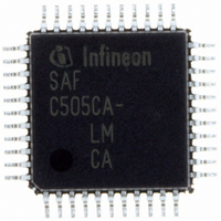
SAF-C515C-8EM CA Infineon Technologies, SAF-C515C-8EM CA Datasheet - Page 60

SAF-C515C-8EM CA
Manufacturer Part Number
SAF-C515C-8EM CA
Description
IC MCU 8BIT OTP MQFP-80-1
Manufacturer
Infineon Technologies
Series
C5xx/C8xxr
Datasheet
1.SAF-C515C-8EM_CA.pdf
(96 pages)
Specifications of SAF-C515C-8EM CA
Core Processor
C500
Core Size
8-Bit
Speed
10MHz
Connectivity
CAN, EBI/EMI, SPI, UART/USART
Peripherals
POR, PWM, WDT
Number Of I /o
49
Program Memory Size
64KB (64K x 8)
Program Memory Type
OTP
Ram Size
2.5K x 8
Voltage - Supply (vcc/vdd)
4.25 V ~ 5.5 V
Data Converters
A/D 8x10b
Oscillator Type
External
Operating Temperature
-40°C ~ 85°C
Package / Case
80-SQFP
Data Bus Width
8 bit
Data Ram Size
2.25 KB
Interface Type
USART, SSC
Maximum Clock Frequency
10 MHz
Number Of Programmable I/os
49
Number Of Timers
3
Operating Supply Voltage
5 V
Maximum Operating Temperature
+ 85 C
Mounting Style
SMD/SMT
Minimum Operating Temperature
- 40 C
On-chip Adc
10 bit, 8 Channel
Packages
PG-MQFP-80
Max Clock Frequency
10.0 MHz
Sram (incl. Cache)
2.25 KByte
Can Nodes
1
A / D Input Lines (incl. Fadc)
8
Program Memory
64.0 KByte
Lead Free Status / RoHS Status
Lead free / RoHS Compliant
Eeprom Size
-
Lead Free Status / Rohs Status
Details
Other names
F515C8EMCANP
F515C8EMCAXT
SAF-C515C-8EMCA
SAF-C515C-8EMCA
SAF-C515C-8EMCAIN
SAFC515C8EMCAX
SP000068749
SP000106399
F515C8EMCAXT
SAF-C515C-8EMCA
SAF-C515C-8EMCA
SAF-C515C-8EMCAIN
SAFC515C8EMCAX
SP000068749
SP000106399
Power Saving Modes
The C515C provides two basic power saving modes, the idle mode and the power down
mode. Additionally, a slow down mode is available. This power saving mode reduces the
internal clock rate in normal operating mode and it can be also used for further power
reduction in idle mode.
• Idle mode
• Power down mode
• Slow-down mode
Table 11
modes.
In the power down mode of operation,
consumption. It must be ensured, however, that
down mode is invoked, and that
power down mode is terminated.
If e.g. the idle mode is left through an interrupt, the microcontroller state (CPU, ports,
peripherals) remains preserved. If a power saving mode is left by a hardware reset, the
microcontroller state is disturbed and replaced by the reset state of the C515C.
If WS (bit 4) is SFR PCON1 is set (C515C-8E only), pin P4.7/RXDC is alternatively
selected as wake-up pin for the software power down mode. If WS (bit 4) is SFR PCON1
is cleared (C515C-8E only), pin P3.2/INT0 is selected as wake-up pin for the software
power down mode.
For the C515C-8R, P3.2/INT0 is always selected as wake-up pin.
Data Sheet
The CPU is gated off from the oscillator. All peripherals are still provided with the clock
and are able to work. Idle mode is entered by software and can be left by an interrupt
or reset.
The operation of the C515C is completely stopped and the oscillator is turned off. This
mode is used to save the contents of the internal RAM with a very low standby current.
Software power down mode: Software power down mode is entered by software
and can be left by reset or by a short low pulse at pin P3.2/INT0 (or P4.7/RXDC,
C515C-8E only).
Hardware power down mode: Hardware power down mode is entered when the pin
HWPD is put to low level.
The controller keeps up the full operating functionality, but its normal clock frequency
is internally divided by 32. This slows down all parts of the controller, the CPU and all
peripherals, to 1/32
significantly reduces power consumption. The slow down mode can be combined with
the idle mode.
gives a general overview of the entry and exit conditions of the power saving
th
of their normal operating frequency. Slowing down the frequency
V
DD
is restored to its normal operating level, before the
56
V
DD
can be reduced to minimize power
V
DD
is not reduced before the power
C515C
2003-02


