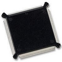
MC68HC16Z1CEH25 Freescale Semiconductor, MC68HC16Z1CEH25 Datasheet - Page 381

MC68HC16Z1CEH25
Manufacturer Part Number
MC68HC16Z1CEH25
Description
IC MCU 16BIT 25MHZ 132-PQFP
Manufacturer
Freescale Semiconductor
Series
HC16r
Datasheet
1.MC68HC16Z1VEH16.pdf
(500 pages)
Specifications of MC68HC16Z1CEH25
Core Processor
CPU16
Core Size
16-Bit
Speed
25MHz
Connectivity
EBI/EMI, SCI, SPI
Peripherals
POR, PWM, WDT
Number Of I /o
16
Program Memory Type
ROMless
Ram Size
1K x 8
Voltage - Supply (vcc/vdd)
2.7 V ~ 5.5 V
Data Converters
A/D 8x10b
Oscillator Type
Internal
Operating Temperature
-40°C ~ 85°C
Package / Case
132-QFP
Package
132PQFP
Family Name
HC16
Maximum Speed
25 MHz
Operating Supply Voltage
3.3|5 V
Data Bus Width
16 Bit
Number Of Programmable I/os
16
On-chip Adc
8-chx10-bit
Number Of Timers
11
Controller Family/series
68HC16
No. Of I/o's
16
Ram Memory Size
1KB
Cpu Speed
25MHz
No. Of Timers
2
Embedded Interface Type
QSPI, SCI
Rohs Compliant
Yes
Processor Series
HC16Z
Core
CPU16
Data Ram Size
1 KB
Interface Type
SCI, SPI, UART
Maximum Clock Frequency
25 MHz
Maximum Operating Temperature
+ 85 C
Mounting Style
SMD/SMT
Minimum Operating Temperature
- 40 C
Lead Free Status / RoHS Status
Lead free / RoHS Compliant
Eeprom Size
-
Program Memory Size
-
Lead Free Status / Rohs Status
Details
Available stocks
Company
Part Number
Manufacturer
Quantity
Price
Company:
Part Number:
MC68HC16Z1CEH25
Manufacturer:
Freescale Semiconductor
Quantity:
135
Company:
Part Number:
MC68HC16Z1CEH25
Manufacturer:
Freescale Semiconductor
Quantity:
10 000
- Current page: 381 of 500
- Download datasheet (6Mb)
MM — Module Mapping
IARB[3:0] — Interrupt Arbitration ID
D.2.2 System Integration Test Register
SIMTR — System Integration Test Register
D.2.3 Clock Synthesizer Control Register
SYNCR — Clock Synthesizer Control Register
M68HC16 Z SERIES
USER’S MANUAL
NOTES:
15
W
0
The logic state of the MM determines the value of ADDR23 for IMB module addresses.
Because ADDR[23:20] are driven to the same state as ADDR19, MM must be set to
one. If MM is cleared, IMB modules are inaccessible to the CPU16. This bit can be
written only once after reset.
Each module that can generate interrupts, including the SIM, has an IARB field. Each
IARB field can be assigned a value from $0 to $F. During an interrupt acknowledge
cycle, IARB permits arbitration among simultaneous interrupts of the same priority
level. The reset value of the SIM IARB field is $F, the highest priority. This prevents
SIM interrupts from being discarded during system initialization.
Used for factory test only.
RESET:
This register determines system clock operating frequency and operation during low-
power stop mode. With a slow reference frequency between 25 and 50 kHz (typically
a 32.768-kHz crystal), the clock frequency is determined by the following equation:
With a fast reference frequency between 1 and 6 MHz (typically a 4.194-MHz crystal),
the reference frequency is divided by 128 before it is passed to the PLL system. The
clock frequency is determined by the following equation:
1. Ensure that the software does not change the value of these bits. They should always be zero.
0 = Internal modules are addressed from $7FF000 – $7FFFFF.
1 = Internal modules are addressed from $FFF000 – $FFFFFF.
14
X
0
13
1
12
1
11
Freescale Semiconductor, Inc.
1
Y[5:0]
For More Information On This Product,
10
1
f
f
sys
Go to: www.freescale.com
9
1
sys
REGISTER SUMMARY
=
=
8
1
--------- - 4 Y
128
f
f
ref
ref
EDIV
7
0
4 Y
+
+
6
0
0
1
1
2
2
5
0
0
2W
2W
+
+
RSVD
X
X
4
0
1
SLOCK
U
3
RSVD
2
0
1
$YFFA02
$YFFA04
STSIM
1
0
STEXT
0
0
D-7
Related parts for MC68HC16Z1CEH25
Image
Part Number
Description
Manufacturer
Datasheet
Request
R
Part Number:
Description:
Manufacturer:
Freescale Semiconductor, Inc
Datasheet:
Part Number:
Description:
Manufacturer:
Freescale Semiconductor, Inc
Datasheet:
Part Number:
Description:
Manufacturer:
Freescale Semiconductor, Inc
Datasheet:
Part Number:
Description:
Manufacturer:
Freescale Semiconductor, Inc
Datasheet:
Part Number:
Description:
Manufacturer:
Freescale Semiconductor, Inc
Datasheet:
Part Number:
Description:
Manufacturer:
Freescale Semiconductor, Inc
Datasheet:
Part Number:
Description:
Manufacturer:
Freescale Semiconductor, Inc
Datasheet:
Part Number:
Description:
Manufacturer:
Freescale Semiconductor, Inc
Datasheet:
Part Number:
Description:
Manufacturer:
Freescale Semiconductor, Inc
Datasheet:
Part Number:
Description:
Manufacturer:
Freescale Semiconductor, Inc
Datasheet:
Part Number:
Description:
Manufacturer:
Freescale Semiconductor, Inc
Datasheet:
Part Number:
Description:
Manufacturer:
Freescale Semiconductor, Inc
Datasheet:
Part Number:
Description:
Manufacturer:
Freescale Semiconductor, Inc
Datasheet:
Part Number:
Description:
Manufacturer:
Freescale Semiconductor, Inc
Datasheet:
Part Number:
Description:
Manufacturer:
Freescale Semiconductor, Inc
Datasheet:


