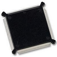
MC68HC16Z1CEH25 Freescale Semiconductor, MC68HC16Z1CEH25 Datasheet - Page 149

MC68HC16Z1CEH25
Manufacturer Part Number
MC68HC16Z1CEH25
Description
IC MCU 16BIT 25MHZ 132-PQFP
Manufacturer
Freescale Semiconductor
Series
HC16r
Datasheet
1.MC68HC16Z1VEH16.pdf
(500 pages)
Specifications of MC68HC16Z1CEH25
Core Processor
CPU16
Core Size
16-Bit
Speed
25MHz
Connectivity
EBI/EMI, SCI, SPI
Peripherals
POR, PWM, WDT
Number Of I /o
16
Program Memory Type
ROMless
Ram Size
1K x 8
Voltage - Supply (vcc/vdd)
2.7 V ~ 5.5 V
Data Converters
A/D 8x10b
Oscillator Type
Internal
Operating Temperature
-40°C ~ 85°C
Package / Case
132-QFP
Package
132PQFP
Family Name
HC16
Maximum Speed
25 MHz
Operating Supply Voltage
3.3|5 V
Data Bus Width
16 Bit
Number Of Programmable I/os
16
On-chip Adc
8-chx10-bit
Number Of Timers
11
Controller Family/series
68HC16
No. Of I/o's
16
Ram Memory Size
1KB
Cpu Speed
25MHz
No. Of Timers
2
Embedded Interface Type
QSPI, SCI
Rohs Compliant
Yes
Processor Series
HC16Z
Core
CPU16
Data Ram Size
1 KB
Interface Type
SCI, SPI, UART
Maximum Clock Frequency
25 MHz
Maximum Operating Temperature
+ 85 C
Mounting Style
SMD/SMT
Minimum Operating Temperature
- 40 C
Lead Free Status / RoHS Status
Lead free / RoHS Compliant
Eeprom Size
-
Program Memory Size
-
Lead Free Status / Rohs Status
Details
Available stocks
Company
Part Number
Manufacturer
Quantity
Price
Company:
Part Number:
MC68HC16Z1CEH25
Manufacturer:
Freescale Semiconductor
Quantity:
135
Company:
Part Number:
MC68HC16Z1CEH25
Manufacturer:
Freescale Semiconductor
Quantity:
10 000
- Current page: 149 of 500
- Download datasheet (6Mb)
5.6.5 Bus Exception Control Cycles
M68HC16 Z SERIES
USER’S MANUAL
An external device or a chip-select circuit must assert at least one of the DSACK[1:0]
signals or the AVEC signal to terminate a bus cycle normally. Bus exception control
cycles are used when bus cycles are not terminated in the expected manner. There
are two sources of bus exception control cycles.
To control termination of a bus cycle for a bus error condition properly, DSACK, BERR,
and HALT must be asserted and negated synchronously with the rising edge of
CLKOUT. This ensures that setup time and hold time requirements are met for the
same falling edge of the MCU clock when two signals are asserted simultaneously.
Refer to
ternal circuitry that provides these signals must be designed with these constraints in
mind, or the internal bus monitor must be used.
Table 5-17
cycles in relation to DSACK assertion.
• Bus error signal (BERR)
• Halt signal (HALT)
— When neither DSACK nor AVEC is asserted within a specified period after as-
— The spurious interrupt monitor asserts internal BERR when an interrupt re-
— External devices can assert BERR to indicate an external bus error.
— HALT can be asserted by an external device to cause single bus cycle opera-
sertion of AS, the internal bus monitor asserts internal BERR.
quest is acknowledged and no IARB contention occurs. BERR assertion termi-
nates a cycle and causes the MCU to process a bus error exception.
tion. HALT is typically used for debugging purposes.
APPENDIX A ELECTRICAL CHARACTERISTICS
is a summary of the acceptable bus cycle terminations for asynchronous
15
0
14
0
Figure 5-16 LPSTOP Interrupt Mask Level
Freescale Semiconductor, Inc.
13
0
For More Information On This Product,
12
0
SYSTEM INTEGRATION MODULE
11
0
Go to: www.freescale.com
10
0
9
0
8
0
7
0
6
0
5
0
4
0
3
0
2
IP MASK
for more information. Ex-
1
LPSTOP MASK LEVEL
0
5-43
Related parts for MC68HC16Z1CEH25
Image
Part Number
Description
Manufacturer
Datasheet
Request
R
Part Number:
Description:
Manufacturer:
Freescale Semiconductor, Inc
Datasheet:
Part Number:
Description:
Manufacturer:
Freescale Semiconductor, Inc
Datasheet:
Part Number:
Description:
Manufacturer:
Freescale Semiconductor, Inc
Datasheet:
Part Number:
Description:
Manufacturer:
Freescale Semiconductor, Inc
Datasheet:
Part Number:
Description:
Manufacturer:
Freescale Semiconductor, Inc
Datasheet:
Part Number:
Description:
Manufacturer:
Freescale Semiconductor, Inc
Datasheet:
Part Number:
Description:
Manufacturer:
Freescale Semiconductor, Inc
Datasheet:
Part Number:
Description:
Manufacturer:
Freescale Semiconductor, Inc
Datasheet:
Part Number:
Description:
Manufacturer:
Freescale Semiconductor, Inc
Datasheet:
Part Number:
Description:
Manufacturer:
Freescale Semiconductor, Inc
Datasheet:
Part Number:
Description:
Manufacturer:
Freescale Semiconductor, Inc
Datasheet:
Part Number:
Description:
Manufacturer:
Freescale Semiconductor, Inc
Datasheet:
Part Number:
Description:
Manufacturer:
Freescale Semiconductor, Inc
Datasheet:
Part Number:
Description:
Manufacturer:
Freescale Semiconductor, Inc
Datasheet:
Part Number:
Description:
Manufacturer:
Freescale Semiconductor, Inc
Datasheet:


