M68EVB908GB60E Freescale Semiconductor, M68EVB908GB60E Datasheet - Page 197
M68EVB908GB60E
Manufacturer Part Number
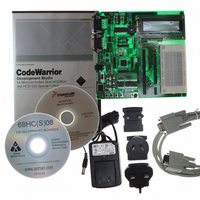
M68EVB908GB60E
Description
BOARD EVAL FOR MC9S08GB60
Manufacturer
Freescale Semiconductor
Type
MCUr
Datasheet
1.M68EVB908GB60E.pdf
(290 pages)
Specifications of M68EVB908GB60E
Contents
Module and Misc Hardware
Processor To Be Evaluated
MC9S08GB
Data Bus Width
8 bit
Interface Type
RS-232
Silicon Manufacturer
Freescale
Core Architecture
HCS08
Core Sub-architecture
HCS08
Silicon Core Number
MC9S08
Silicon Family Name
S08GB
Kit Contents
GB60 Evaluation Kit
Rohs Compliant
Yes
For Use With/related Products
MC9S08GB60
Lead Free Status / RoHS Status
Lead free / RoHS Compliant


12.4.1
This read/write register includes the SPI enable control, interrupt enables, and configuration options.
SPIE — SPI Interrupt Enable (for SPRF and MODF)
SPE — SPI System Enable
SPTIE — SPI Transmit Interrupt Enable
MSTR — Master/Slave Mode Select
CPOL — Clock Polarity
CPHA — Clock Phase
Freescale Semiconductor
This is the interrupt enable for SPI receive buffer full (SPRF) and mode fault (MODF) events.
Disabling the SPI halts any transfer that is in progress, clears data buffers, and initializes internal state
machines. SPRF is cleared and SPTEF is set to indicate the SPI transmit data buffer is empty.
This is the interrupt enable bit for SPI transmit buffer empty (SPTEF).
This bit effectively places an inverter in series with the clock signal from a master SPI or to a slave SPI
device. Refer to
This bit selects one of two clock formats for different kinds of synchronous serial peripheral devices.
Refer to
1 = When SPRF or MODF is 1, request a hardware interrupt.
0 = Interrupts from SPRF and MODF inhibited (use polling).
1 = SPI system enabled.
0 = SPI system inactive.
1 = When SPTEF is 1, hardware interrupt requested.
0 = Interrupts from SPTEF inhibited (use polling).
1 = SPI module configured as a master SPI device.
0 = SPI module configured as a slave SPI device.
1 = Active-low SPI clock (idles high).
0 = Active-high SPI clock (idles low).
1 = First edge on SPSCK occurs at the start of the first cycle of an 8-cycle data transfer.
0 = First edge on SPSCK occurs at the middle of the first cycle of an 8-cycle data transfer.
SPI Control Register 1 (SPI1C1)
Section 12.3.1, “SPI Clock
Section 12.3.1, “SPI Clock
Reset:
Read:
Write:
SPIE
Bit 7
Figure 12-7. SPI Control Register 1 (SPI1C1)
0
MC9S08GB/GT Data Sheet, Rev. 2.3
SPE
Formats,” for more details.
6
0
SPTIE
Formats,”
5
0
MSTR
for more details.
4
0
CPOL
3
0
CPHA
2
1
SPI Registers and Control Bits
SSOE
1
0
LSBFE
Bit 0
0
197
Related parts for M68EVB908GB60E
Image
Part Number
Description
Manufacturer
Datasheet
Request
R

Part Number:
Description:
Manufacturer:
Freescale Semiconductor, Inc
Datasheet:
Part Number:
Description:
Manufacturer:
Freescale Semiconductor, Inc
Datasheet:
Part Number:
Description:
Manufacturer:
Freescale Semiconductor, Inc
Datasheet:
Part Number:
Description:
Manufacturer:
Freescale Semiconductor, Inc
Datasheet:
Part Number:
Description:
Manufacturer:
Freescale Semiconductor, Inc
Datasheet:
Part Number:
Description:
Manufacturer:
Freescale Semiconductor, Inc
Datasheet:
Part Number:
Description:
Manufacturer:
Freescale Semiconductor, Inc
Datasheet:
Part Number:
Description:
Manufacturer:
Freescale Semiconductor, Inc
Datasheet:
Part Number:
Description:
Manufacturer:
Freescale Semiconductor, Inc
Datasheet:
Part Number:
Description:
Manufacturer:
Freescale Semiconductor, Inc
Datasheet:
Part Number:
Description:
Manufacturer:
Freescale Semiconductor, Inc
Datasheet:
Part Number:
Description:
Manufacturer:
Freescale Semiconductor, Inc
Datasheet:
Part Number:
Description:
Manufacturer:
Freescale Semiconductor, Inc
Datasheet:
Part Number:
Description:
Manufacturer:
Freescale Semiconductor, Inc
Datasheet:
Part Number:
Description:
Manufacturer:
Freescale Semiconductor, Inc
Datasheet: