M68EVB908GB60E Freescale Semiconductor, M68EVB908GB60E Datasheet - Page 128
M68EVB908GB60E
Manufacturer Part Number
M68EVB908GB60E
Description
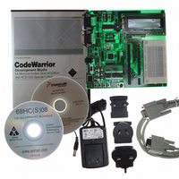
BOARD EVAL FOR MC9S08GB60
Manufacturer
Freescale Semiconductor
Type
MCUr
Datasheet
1.M68EVB908GB60E.pdf
(290 pages)
Specifications of M68EVB908GB60E
Contents
Module and Misc Hardware
Processor To Be Evaluated
MC9S08GB
Data Bus Width
8 bit
Interface Type
RS-232
Silicon Manufacturer
Freescale
Core Architecture
HCS08
Core Sub-architecture
HCS08
Silicon Core Number
MC9S08
Silicon Family Name
S08GB
Kit Contents
GB60 Evaluation Kit
Rohs Compliant
Yes
For Use With/related Products
MC9S08GB60
Lead Free Status / RoHS Status
Lead free / RoHS Compliant


Central Processor Unit (CPU)
8.3.3
This 16-bit address pointer register points at the next available location on the automatic last-in-first-out
(LIFO) stack. The stack may be located anywhere in the 64-Kbyte address space that has RAM and can
be any size up to the amount of available RAM. The stack is used to automatically save the return address
for subroutine calls, the return address and CPU registers during interrupts, and for local variables. The
AIS (add immediate to stack pointer) instruction adds an 8-bit signed immediate value to SP. This is most
often used to allocate or deallocate space for local variables on the stack.
SP is forced to $00FF at reset for compatibility with the earlier M68HC05 Family. HCS08 programs
normally change the value in SP to the address of the last location (highest address) in on-chip RAM
during reset initialization to free up direct page RAM (from the end of the on-chip registers to $00FF).
The RSP (reset stack pointer) instruction was included for compatibility with the M68HC05 Family and
is seldom used in new HCS08 programs because it only affects the low-order half of the stack pointer.
8.3.4
The program counter is a 16-bit register that contains the address of the next instruction or operand to be
fetched.
During normal program execution, the program counter automatically increments to the next sequential
memory location every time an instruction or operand is fetched. Jump, branch, interrupt, and return
operations load the program counter with an address other than that of the next sequential location. This
is called a change-of-flow.
During reset, the program counter is loaded with the reset vector that is located at $FFFE and $FFFF. The
vector stored there is the address of the first instruction that will be executed after exiting the reset state.
8.3.5
The 8-bit condition code register contains the interrupt mask (I) and five flags that indicate the results of
the instruction just executed. Bits 6 and 5 are set permanently to 1. The following paragraphs describe the
functions of the condition code bits in general terms. For a more detailed explanation of how each
instruction sets the CCR bits, refer to the HCS08 Family Reference Manual, volume 1, Freescale
Semiconductor document order number HCS08RMv1/D.
128
Stack Pointer (SP)
Program Counter (PC)
Condition Code Register (CCR)
CONDITION CODE REGISTER
Figure 8-2. Condition Code Register
MC9S08GB/GT Data Sheet, Rev. 2.3
V 1 1 H I N Z
7
C
0
CARRY
ZERO
NEGATIVE
INTERRUPT MASK
HALF-CARRY (FROM BIT 3)
TWO’S COMPLEMENT OVERFLOW
CCR
Freescale Semiconductor
Related parts for M68EVB908GB60E
Image
Part Number
Description
Manufacturer
Datasheet
Request
R

Part Number:
Description:
Manufacturer:
Freescale Semiconductor, Inc
Datasheet:
Part Number:
Description:
Manufacturer:
Freescale Semiconductor, Inc
Datasheet:
Part Number:
Description:
Manufacturer:
Freescale Semiconductor, Inc
Datasheet:
Part Number:
Description:
Manufacturer:
Freescale Semiconductor, Inc
Datasheet:
Part Number:
Description:
Manufacturer:
Freescale Semiconductor, Inc
Datasheet:
Part Number:
Description:
Manufacturer:
Freescale Semiconductor, Inc
Datasheet:
Part Number:
Description:
Manufacturer:
Freescale Semiconductor, Inc
Datasheet:
Part Number:
Description:
Manufacturer:
Freescale Semiconductor, Inc
Datasheet:
Part Number:
Description:
Manufacturer:
Freescale Semiconductor, Inc
Datasheet:
Part Number:
Description:
Manufacturer:
Freescale Semiconductor, Inc
Datasheet:
Part Number:
Description:
Manufacturer:
Freescale Semiconductor, Inc
Datasheet:
Part Number:
Description:
Manufacturer:
Freescale Semiconductor, Inc
Datasheet:
Part Number:
Description:
Manufacturer:
Freescale Semiconductor, Inc
Datasheet:
Part Number:
Description:
Manufacturer:
Freescale Semiconductor, Inc
Datasheet:
Part Number:
Description:
Manufacturer:
Freescale Semiconductor, Inc
Datasheet: