AT91SAM9M10-G45-EK Atmel, AT91SAM9M10-G45-EK Datasheet - Page 777
AT91SAM9M10-G45-EK
Manufacturer Part Number
AT91SAM9M10-G45-EK
Description
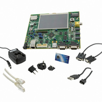
KIT EVAL FOR AT91SAMG45/9M10
Manufacturer
Atmel
Series
AT91SAM Smart ARMr
Type
MCUr
Specifications of AT91SAM9M10-G45-EK
Contents
Board, Cables, Power Supply
Processor To Be Evaluated
AT91SAM9M10
Processor Series
AT91SAM9
Data Bus Width
32 bit
Interface Type
RS-232, Ethernet, USB, JTAG
Operating Supply Voltage
5 V
Silicon Manufacturer
Atmel
Core Architecture
AVR
Kit Contents
Board
Features
Two High Speed USB Hosts, LCD TFT Display
Svhc
No SVHC (15-Dec-2010)
Mcu Supported Families
AT91SAM9M10,
Rohs Compliant
Yes
For Use With/related Products
AT91SAM9M10
Lead Free Status / RoHS Status
Lead free / RoHS Compliant
Available stocks
Company
Part Number
Manufacturer
Quantity
Price
Company:

Part Number:
AT91SAM9M10-G45-EK
Manufacturer:
INFINEON
Quantity:
10 000
Company:
Part Number:
AT91SAM9M10-G45-EK
Manufacturer:
Atmel
Quantity:
135


36.5
36.5.1
36.5.1.1
36.5.1.2
Figure 36-2. Receive Buffer List
6355B–ATARM–21-Jun-10
Programming Interface
Initialization
Configuration
Receive Buffer List
Receive Buffer Queue Pointer
(MAC Register)
Initialization of the EMAC configuration (e.g., loop-back mode, frequency ratios) must be done
while the transmit and receive circuits are disabled. See the description of the network control
register and network configuration register earlier in this document.
To change loop-back mode, the following sequence of operations must be followed:
Note:
Receive data is written to areas of data (i.e., buffers) in system memory. These buffers are listed
in another data structure that also resides in main memory. This data structure (receive buffer
queue) is a sequence of descriptor entries as defined in
page
To create the list of buffers:
1. Write to network control register to disable transmit and receive circuits.
2. Write to network control register to change loop-back mode.
3. Write to network control register to re-enable transmit or receive circuits.
1. Allocate a number (n) of buffers of 128 bytes in system memory.
2. Allocate an area 2n words for the receive buffer descriptor entry in system memory and
3. If less than 1024 buffers are defined, the last descriptor must be marked with the wrap
4. Write address of receive buffer descriptor entry to EMAC register receive_buffer
5. The receive circuits can then be enabled by writing to the address recognition registers
766. It points to this data structure.
create n entries in this list. Mark all entries in this list as owned by EMAC, i.e., bit 0 of
word 0 set to 0.
bit (bit 1 in word 0 set to 1).
queue pointer.
and then to the network control register.
These writes to network control register cannot be combined in any way.
Receive Buffer Descriptor List
(In memory)
“Receive Buffer Descriptor Entry” on
Receive Buffer 1
Receive Buffer 0
Receive Buffer N
(In memory)
AT91SAM9M10
777
Related parts for AT91SAM9M10-G45-EK
Image
Part Number
Description
Manufacturer
Datasheet
Request
R

Part Number:
Description:
KIT EVAL FOR AT91SAM9M10
Manufacturer:
Atmel
Datasheet:

Part Number:
Description:
IC MCU 16/32BIT ARM9 324TFBGA
Manufacturer:
Atmel
Datasheet:

Part Number:
Description:
At91 Arm Thumb-based Microcontrollers
Manufacturer:
ATMEL Corporation
Datasheet:

Part Number:
Description:
MCU, MPU & DSP Development Tools KICKSTART KIT FOR AT91SAM9 PLUS
Manufacturer:
IAR Systems

Part Number:
Description:
DEV KIT FOR AVR/AVR32
Manufacturer:
Atmel
Datasheet:
Part Number:
Description:
INTERVAL AND WIPE/WASH WIPER CONTROL IC WITH DELAY
Manufacturer:
ATMEL Corporation
Datasheet:
Part Number:
Description:
Low-Voltage Voice-Switched IC for Hands-Free Operation
Manufacturer:
ATMEL Corporation
Datasheet:
Part Number:
Description:
MONOLITHIC INTEGRATED FEATUREPHONE CIRCUIT
Manufacturer:
ATMEL Corporation
Datasheet:
Part Number:
Description:
AM-FM Receiver IC U4255BM-M
Manufacturer:
ATMEL Corporation
Datasheet:
Part Number:
Description:
Monolithic Integrated Feature Phone Circuit
Manufacturer:
ATMEL Corporation
Datasheet:
Part Number:
Description:
Multistandard Video-IF and Quasi Parallel Sound Processing
Manufacturer:
ATMEL Corporation
Datasheet:
Part Number:
Description:
High-performance EE PLD
Manufacturer:
ATMEL Corporation
Datasheet: