MC56F8037EVM Freescale Semiconductor, MC56F8037EVM Datasheet - Page 121
MC56F8037EVM
Manufacturer Part Number
MC56F8037EVM
Description
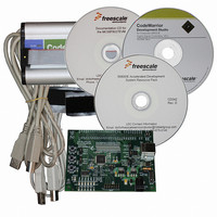
BOARD EVAL FOR MC56F8037
Manufacturer
Freescale Semiconductor
Type
MCUr
Datasheet
1.MC56F8037EVM.pdf
(180 pages)
Specifications of MC56F8037EVM
Contents
Board, Cables, CD, Debugger
Silicon Manufacturer
Freescale
Core Architecture
56800/E
Core Sub-architecture
56800/E
Silicon Core Number
MC56F
Silicon Family Name
MC56F80xx
Kit Contents
MC56F8037EVM, USB-JTAG Adapter, Cables, CD
Rohs Compliant
Yes
For Use With/related Products
MC56F8037
Lead Free Status / RoHS Status
Lead free / RoHS Compliant
Available stocks
Company
Part Number
Manufacturer
Quantity
Price
Company:

Part Number:
MC56F8037EVM
Manufacturer:
Freescale Semiconductor
Quantity:
135


6.3.21.5
This bit field is reserved. Each bit must be set to 0.
6.3.21.6
This field selects the alternate input source signal to feed PWM input PSRC2 as the PWM4/PWM5 pair
source.
6.3.21.7
This field selects the alternate input source signal to feed PWM input PSRC1 as the PWM2/PWM3 pair
source.
6.3.21.8
This field selects the alternate input source signal to feed PWM input PSRC0 as the PWM0/PWM1 pair
source.
Freescale Semiconductor
•
•
•
•
•
•
•
•
•
•
•
•
•
•
000 = I/O Pin (External) - Use a PSRC2 input pin as PWM source (default)
001 = TA3 (Internal) - Use Timer A3 output as PWM source
010 = ADC SAMPLE2 (Internal) - Use ADC SAMPLE2 result as PWM source
— If the ADC conversion result in SAMPLE2 is greater than the value programmed into the High Limit
— If the ADC conversion result in SAMPLE2 is less than the value programmed into the Low Limit
011 = CMPAO (Internal) - Use Comparator A output as PWM source
100 = CMPBO (Internal) - Use Comparator B output as PWM source
11x = Reserved
1x1 = Reserved
000 = I/O pin (External) - Use a PSRC1 input pin as PWM source (default)
001 = TA2 (Internal) - Use Timer A2 output as PWM source
010 = ADC SAMPLE1 (Internal) - Use ADC SAMPLE1 result as PWM source
— If the ADC conversion result in SAMPLE1 is greater than the value programmed into the High Limit
— If the ADC conversion result in SAMPLE1 is less than the value programmed into the Low Limit
011 = CMPAO (Internal) - Use Comparator A output as PWM source
100 = CMPBO (Internal) - Use Comparator B output as PWM source
11x = Reserved
1x1 = Reserved
register HLMT2, then PWM4 is set to 0 and PWM5 is set to 1
register LLMT2, then PWM4 is set to 1 and PWM5 is set to 0
register HLMT1, then PWM2 is set to 0 and PWM3 is set to 1
register LLMT1, then PWM2 is set to 1 and PWM3 is set to 0
Reserved—Bits 10–9
Select Peripheral Input Source for PWM4/PWM5 Pair Source
(IPS0_PSRC2)—Bits 8–6
Select Peripheral Input Source for PWM2/PWM3 Pair Source
(IPS0_PSRC1)—Bits 5–3
Select Peripheral Input Source for PWM0/PWM1 Pair Source
(IPS0_PSRC0)—Bits 2–0
56F8037/56F8027 Data Sheet, Rev. 7
Register Descriptions
121
Related parts for MC56F8037EVM
Image
Part Number
Description
Manufacturer
Datasheet
Request
R

Part Number:
Description:
Manufacturer:
Freescale Semiconductor, Inc
Datasheet:
Part Number:
Description:
Manufacturer:
Freescale Semiconductor, Inc
Datasheet:
Part Number:
Description:
Manufacturer:
Freescale Semiconductor, Inc
Datasheet:
Part Number:
Description:
Manufacturer:
Freescale Semiconductor, Inc
Datasheet:
Part Number:
Description:
Manufacturer:
Freescale Semiconductor, Inc
Datasheet:
Part Number:
Description:
Manufacturer:
Freescale Semiconductor, Inc
Datasheet:
Part Number:
Description:
Manufacturer:
Freescale Semiconductor, Inc
Datasheet:
Part Number:
Description:
Manufacturer:
Freescale Semiconductor, Inc
Datasheet:
Part Number:
Description:
Manufacturer:
Freescale Semiconductor, Inc
Datasheet:
Part Number:
Description:
Manufacturer:
Freescale Semiconductor, Inc
Datasheet:
Part Number:
Description:
Manufacturer:
Freescale Semiconductor, Inc
Datasheet:
Part Number:
Description:
Manufacturer:
Freescale Semiconductor, Inc
Datasheet:
Part Number:
Description:
Manufacturer:
Freescale Semiconductor, Inc
Datasheet:
Part Number:
Description:
Manufacturer:
Freescale Semiconductor, Inc
Datasheet:
Part Number:
Description:
Manufacturer:
Freescale Semiconductor, Inc
Datasheet: