MC56F8037EVM Freescale Semiconductor, MC56F8037EVM Datasheet - Page 102
MC56F8037EVM
Manufacturer Part Number
MC56F8037EVM
Description
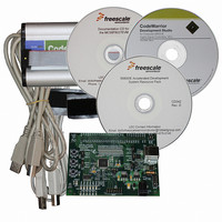
BOARD EVAL FOR MC56F8037
Manufacturer
Freescale Semiconductor
Type
MCUr
Datasheet
1.MC56F8037EVM.pdf
(180 pages)
Specifications of MC56F8037EVM
Contents
Board, Cables, CD, Debugger
Silicon Manufacturer
Freescale
Core Architecture
56800/E
Core Sub-architecture
56800/E
Silicon Core Number
MC56F
Silicon Family Name
MC56F80xx
Kit Contents
MC56F8037EVM, USB-JTAG Adapter, Cables, CD
Rohs Compliant
Yes
For Use With/related Products
MC56F8037
Lead Free Status / RoHS Status
Lead free / RoHS Compliant
Available stocks
Company
Part Number
Manufacturer
Quantity
Price
Company:

Part Number:
MC56F8037EVM
Manufacturer:
Freescale Semiconductor
Quantity:
135


6.3.8
By default, all peripherals are clocked at the system clock rate, which has a maximum of 32MHz. Selected
peripherals clocks have the option to be clocked at 3X system clock rate, which has a maximum of 96MHz,
if the PLL output clock is selected as the system clock. If PLL is disabled, the 3X system clock will not be
available. This register is used to enable high-speed clocking for those peripherals that support it.
Note:
6.3.8.1
This bit selects the clock speed for the Quad Timer B module.
6.3.8.2
This bit selects the clock speed for the Quad Timer A module.
6.3.8.3
This bit selects the clock speed for the PWM module.
6.3.8.4
This bit selects the clock speed for the I
6.3.8.5
This bit field is reserved. Each bit must be set to 0.
102
•
•
•
•
•
•
•
•
Base + $B
RESET
Read
Write
0 = Quad Timer B clock rate equals the system clock rate, to a maximum 32MHz (default)
1 = Quad Timer B clock rate equals 3X system clock rate, to a maximum 96MHz
0 = Quad Timer A clock rate equals the system clock rate, to a maximum 32MHz (default)
1 = Quad Timer A clock rate equals 3X system clock rate, to a maximum 96MHz
0 = PWM module clock rate equals the system clock rate, to a maximum 32MHz (default)
1 = PWM module clock rate equals 3X system clock rate, to a maximum 96MHz
0 = I
1 = I
Peripheral Clock Rate Register (SIM_PCR)
Operation is unpredictable if peripheral clocks are reconfigured at runtime, so peripherals should be
disabled before a peripheral clock is reconfigured.
2
2
Quad Timer B Clock Rate (TMRB_CR)—Bit 15
Quad Timer A Clock Rate (TMRA_CR)—Bit 14
Pulse Width Modulator Clock Rate (PWM_CR)—Bit 13
Inter-Integrated Circuit Run Clock Rate (I2C_CR)—Bit 12
C module run clock rate equals the system clock rate, to a maximum 32MHz (default)
C module run clock rate equals 3X system clock rate, to a maximum 96MHz
Reserved—Bits 11–0
TMRB_
CR
15
0
Figure 6-9 Peripheral Clock Rate Register (SIM_PCR)
TMRA_
CR
14
0
PWM_
CR
13
0
I2C_
CR
12
0
56F8037/56F8027 Data Sheet, Rev. 7
2
11
C run clock.
0
0
10
0
0
9
0
0
8
0
0
7
0
0
6
0
0
5
0
0
4
0
0
Freescale Semiconductor
3
0
0
2
0
0
1
0
0
0
0
0
Related parts for MC56F8037EVM
Image
Part Number
Description
Manufacturer
Datasheet
Request
R

Part Number:
Description:
Manufacturer:
Freescale Semiconductor, Inc
Datasheet:
Part Number:
Description:
Manufacturer:
Freescale Semiconductor, Inc
Datasheet:
Part Number:
Description:
Manufacturer:
Freescale Semiconductor, Inc
Datasheet:
Part Number:
Description:
Manufacturer:
Freescale Semiconductor, Inc
Datasheet:
Part Number:
Description:
Manufacturer:
Freescale Semiconductor, Inc
Datasheet:
Part Number:
Description:
Manufacturer:
Freescale Semiconductor, Inc
Datasheet:
Part Number:
Description:
Manufacturer:
Freescale Semiconductor, Inc
Datasheet:
Part Number:
Description:
Manufacturer:
Freescale Semiconductor, Inc
Datasheet:
Part Number:
Description:
Manufacturer:
Freescale Semiconductor, Inc
Datasheet:
Part Number:
Description:
Manufacturer:
Freescale Semiconductor, Inc
Datasheet:
Part Number:
Description:
Manufacturer:
Freescale Semiconductor, Inc
Datasheet:
Part Number:
Description:
Manufacturer:
Freescale Semiconductor, Inc
Datasheet:
Part Number:
Description:
Manufacturer:
Freescale Semiconductor, Inc
Datasheet:
Part Number:
Description:
Manufacturer:
Freescale Semiconductor, Inc
Datasheet:
Part Number:
Description:
Manufacturer:
Freescale Semiconductor, Inc
Datasheet: